
What Is CNC Turning?
CNC turning holds a rotating workpiece and cuts it with stationary tools. This page covers the mechanism, the axes, the tolerances you can expect, and the part shapes where turning is the right call.
In this article
- 1
- 2
- 3
- 4
- 5
- 6
- 7
What Is CNC Turning and How Does It Remove Material?
A lathe spins the workpiece. The cutting tool does not rotate. That single fact separates turning from milling, and it explains almost everything else about the process. On a CNC lathe the spindle holds the blank in a chuck or collet and rotates it, while a turret carries turning tools, boring bars, drills and taps into the cut.
The controller reads a program written in G-code and moves the turret along X and Z on a basic two-axis lathe. X controls radial position, Z controls travel along the spindle axis. Material comes off as a continuous chip when conditions are right, or as a tangle when they are not. Surface finish, tool life and dimensional accuracy all follow from the choice of speed, feed and depth of cut.
Because the part rotates around a fixed centerline, every feature cut on a lathe is concentric to that centerline. This is the hidden advantage of turning. You do not have to re-fixture a part to keep a bore and an outside diameter running true to each other. They are true by construction, as long as the part stays in the same chuck.
The trade-off is symmetry. A lathe is excellent at surfaces of revolution and weak at anything off-axis. Flat faces, slots and bolt-hole patterns that do not sit on the centerline need a second operation, a live tool, or a different machine.
Spindle, Turret, Guideways and Tailstock: What Each Part Does
The spindle is the heart of the machine. Its bearings set the ceiling on roundness and finish. A machine running at 4,000 rpm with a warm spindle will hold size better than the same machine started cold, which is why we let spindles idle up to temperature before a tight-tolerance run.
The turret indexes tools into position. A gang-tool lathe skips the turret and mounts every tool on one plate, which is faster for small parts but limits how many tools you can carry. Turrets trade a little indexing time for capacity, and that normally wins on parts with several diameters and a thread.
Guideways decide how the machine behaves under load. Box ways are heavily damped and resist chatter on deep cuts. Linear guides move faster and hold positioning accuracy over long travel. Both appear in our shop, and the choice matches the part.
The tailstock supports the free end of a long shaft. Past roughly three times the diameter in unsupported length, a shaft will deflect and cut tapered. If a drawing calls for a long slender journal, plan on a tailstock or a steady rest, and expect us to ask about it.
Two, Three and Five Axis Turning Explained
A two-axis lathe is the baseline. X and Z only. It cuts outside diameters, faces, grooves, chamfers, threads and bores with a boring bar. For a simple bushing or a spacer, nothing beats it on cost per part.
Add a C axis and driven tools and you get a mill-turn lathe. The spindle can index and hold position, so the turret can drill an off-center hole or mill a flat without a second setup. Parts with a few cross features move through in one cycle instead of two.
Five-axis turning machines, including the 16 simultaneous 5-axis centers in our shop, tilt the tool or the work to reach compound angles. This matters for impellers, medical instruments and hydraulic fittings with angled ports. It also shortens setups, which is where most of the accuracy is lost on a multi-operation part.
More axes are not automatically better. A three-axis lathe with a good fixture often beats a five-axis machine on a simple turned part, because programming and cycle time stay low. Match the axis count to the geometry, not to the spec sheet.
Speeds, Feeds and the Numbers Behind a Clean Cut
Cutting speed is surface speed, not spindle rpm. A Ø50 mm aluminum bar at 200 m/min needs a very different rpm than a Ø10 mm stainless pin at the same surface speed. The controller does that math when you program constant surface speed with G96.
Feed per revolution sets the chip thickness and, on a finish pass, the theoretical surface finish. A 0.8 mm nose radius at 0.1 mm/rev gives a much smoother finish than the same tool at 0.3 mm/rev. This is arithmetic, not opinion, and it is why we set feed from the finish callout rather than from habit.
Depth of cut decides how many passes a feature takes. Roughing removes material fast with heavy depth and moderate speed. Finishing takes a light pass at higher speed. Mixing the two into one pass usually ends with chatter marks and a short tool life.
On our lathes we hold ±0.005 mm (±0.0002 in) on turned diameters. Fine finishes land at Ra 0.2–0.8 μm when the geometry allows, and Ra 0.8–1.6 μm is routine. Those numbers assume a rigid setup and a material that behaves.
Which Materials Turn Well and Which Fight Back
Free-machining aluminum and brass are the easy cases. 6061-T6, 2024 and 7075 cut cleanly at high surface speed and hold a sharp edge. C36000 brass is the classic screw-machine material. If a part is a small turned fitting, brass or aluminum is usually the budget answer.
Stainless 303 turns far better than 304 because of the added sulfur. When a drawing calls for 304 or 316L, expect slower speeds, more tool wear and a higher chance of built-up edge. 17-4PH in the H1150 condition machines reasonably; in the annealed condition it is gummy.
Titanium TC4 (Ti-6Al-4V) and Inconel are the hard cases. They conduct heat poorly, so the cutting edge absorbs it. Speeds drop, carbide grades change, and coolant delivery matters more than on any other material. Turning them is possible. Turning them cheaply is not.
Plastics turn with sharp, polished tools and high rake angles. PEEK and POM machine well. ABS and PP tend to smear and need air blast rather than flood coolant to clear chips. Carbon fibre needs diamond or coated tooling to survive the abrasion.
Where Turning Stops Being the Right Answer
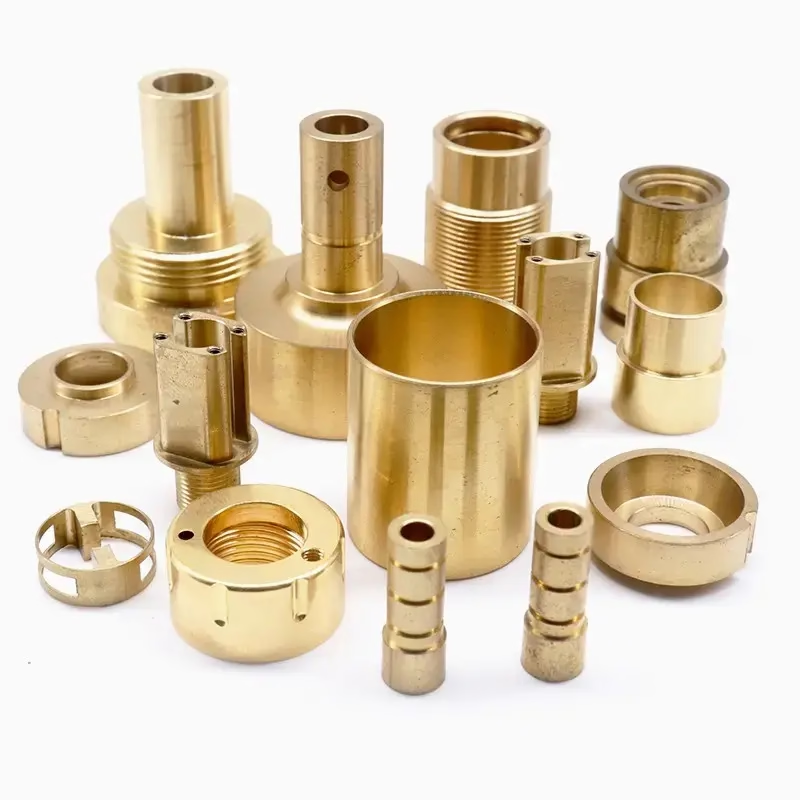
Turning wins on parts that are round or have cylindrical features. Shafts, bushings, spacers, fittings, pistons, valve bodies, threaded inserts, rollers and flanges all belong on a lathe. If the drawing is a solid of revolution plus a few holes, turning is almost always the cheapest route.
Turning loses on thin flat plates, deep rectangular pockets and parts with a lot of material removed away from the centerline. A mill removes that material with a rigid tool in a straight line. A lathe would need a second operation for every feature.
Tolerance is rarely the deciding factor. Both processes reach ±0.005 mm when the setup is right. The real question is how many setups a part needs. Every extra setup adds stack-up error and lead time, and turning usually needs fewer of them on round work.
Aspect ratio is the other boundary. Long slender shafts deflect under cutting force. Past a certain length-to-diameter ratio, you add a tailstock, a steady rest or a follow rest, and the cost climbs with each addition. Send us the drawing and we will tell you which one applies.
Turning vs Milling: Which Process Fits the Part
Pick by geometry first, then by tolerance and volume.
| Factor | CNC Turning | CNC Milling |
|---|---|---|
| Workpiece motion | Rotates | Stationary |
| Tool motion | Stationary, indexes | Rotates and travels |
| Best geometry | Round, cylindrical, threaded | Prismatic, pockets, slots |
| Typical tolerance | ±0.005 mm on diameters | ±0.005 mm on features |
| Off-axis holes | Needs live tool or second op | Built into the cycle |
| Setup for round parts | One chuck, one op | Fixture and multiple ops |
| Small round volume | Very low cost per part | Higher cost per part |
| Flat plates | Poor fit | Correct choice |
The Short Version
If the part is round, threaded or has a bore on the centerline, turn it. If it is flat, pocketed or mostly off-axis, mill it. When a part is both, a mill-turn lathe usually beats two separate setups.
CNC Turning Questions Engineers Ask
What tolerance can a lathe actually hold?
On our machines we hold ±0.005 mm (±0.0002 in) on turned diameters under normal production conditions. That assumes a rigid setup, a stable material and a spindle at working temperature.
Tighter callouts are possible on specific features, but they need a conversation. The limit usually comes from thermal drift and chuck repeatability, not from the controller resolution.
Can a lathe drill and tap holes?
Yes. A turret can carry drills, taps and boring bars, and they work on the centerline in the same cycle as the turning. Off-center holes need a C axis with driven tools or a second milling operation.
For a part with four bolt holes on a flange face, a mill-turn lathe finishes the whole part in one cycle. A two-axis lathe would need a mill for the holes.
Why does my turned part come out tapered?
The usual cause is workpiece deflection on a long, unsupported shaft. Cutting force pushes the free end away from the tool, so the diameter grows toward the tailstock end.
Add a tailstock or a steady rest, reduce depth of cut, or take a spring pass. Tool wear and a misaligned tailstock cause the same symptom, so check both before rewriting the program.
Is turning cheaper than milling?
For round parts, usually yes. A lathe needs one chuck setup to produce a diameter, a face, a thread and a bore. A mill would need a fixture and several operations for the same result.
For flat or prismatic parts the answer flips. Milling removes material from a plate in one setup, while turning has no natural way to hold it.
What surface finish should I specify?
Ra 0.8–1.6 μm is a normal turned finish and costs nothing extra. Ra 0.2–0.8 μm is achievable with a light finishing pass and a sharp tool, but it adds cycle time.
Do not specify a finer finish than the function needs. A sealing surface may need Ra 0.4 μm. A bracket that only needs to fit does not.
Can you turn parts from a single prototype to production?
Yes. We run from one prototype to 10,000+ part runs with no minimum order quantity on the turning side.
Quotation and a free DFM analysis come back within 12 hours, and production can start within 24 hours once the drawing and material are confirmed.
Send Us Your Turned Part
Upload a drawing and we will return a quote with a DFM note on setup, tolerance and material within 12 hours.
12-hour quoteNo minimum order quantity100% inspection before shipment
More Machining Notes
We publish setup notes, tooling trials and inspection data from the factory floor.











