
What Is a CNC System for Machine Tools?
A CNC system for machine tools is the control chain that reads a program and drives the axes, spindle and tool changer to cut a part. This page explains what sits inside that chain, where accuracy actually comes from, and which jobs it cannot solve. Written for engineers and buyers who have to judge a process, not a brochure.
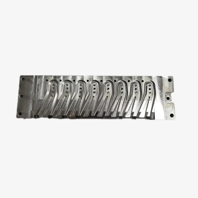
What a CNC system for machine tools actually contains
Strip the cabinet doors off and a CNC system for machine tools is four things talking to each other: a program, a controller, servo drives with feedback, and the machine structure. The program is a list of coordinates and switching commands from a CAM post-processor. The controller reads that list and turns it into motion commands thousands of times per second. The drives push the ballscrews and rotary tables. Feedback closes the loop.
The controller is the part people mean when they say CNC. It runs a real-time loop: read the encoder, compare with the commanded position, adjust the current to the motor. A typical position loop closes at 1–4 kHz. Between those ticks the controller also does look-ahead, taking 100 or more blocks of toolpath and limiting acceleration so the machine does not overshoot a corner.
That look-ahead is why a modern machine holds a corner better than an older one at the same feed rate. The mechanics did not change much. The planning did.
Everything downstream depends on the same data. If the CAM output has a wrong tool radius, the controller will execute the error perfectly. A CNC system is obedient, not clever.
- 1ProgramG-code and M-code from a post-processor, or a native format on some controls
- 2ControllerInterpolates axes, closes the position loop, manages offsets and tool data
- 3Drives and feedbackServo amplifiers plus encoders or linear scales on the moving elements
- 4Machine structureBallscrews, guides, spindle, rotary table, and the thermal mass around them
Accuracy is a system property, not a controller number
A control resolution of 0.1 μm appears on datasheets, but no machine cuts to 0.1 μm repeatably. The real error budget is spread across the whole chain. Ballscrew pitch error, guide straightness, spindle thermal growth, tool deflection and fixture stiffness all contribute, and the largest term usually wins.
Thermal drift is the one people underestimate. A spindle running at 12,000 rpm for two hours grows in Z. If the machine has no thermal compensation, a tight tolerance on a long run will walk. On our 5-axis centers we hold ±0.005 mm on features that fit the working envelope, and we usually reach it by controlling the process, not by trusting the spec sheet.
Stiffness matters more than resolution for most parts. A light finishing pass at 0.05 mm radial depth on a long tool will deflect more than the machine can correct. That is a tooling and setup problem, not a control problem.
So when a drawing asks for ±0.005 mm, the question is not which controller is installed. The question is whether the feature can be reached by a stiff setup, a short tool, and a process that has been proven on the same material.
- 1Machine geometrySquareness and straightness of the axes set the floor for any tolerance
- 2Thermal behaviorWarm-up cycles and compensation reduce drift during long runs
- 3Tool and holderRunout and length-to-diameter ratio often dominate the error budget
- 4FixtureA weak hold-down shows up as chatter and taper, not as a control fault
How axis count changes what the CNC system can cut
A 3-axis machine moves the tool in X, Y and Z while the part stays fixed. It cuts prismatic parts well: plates, housings, brackets, pockets with vertical walls. Most of the world's machined parts are still made this way, and it is the cheapest route when the geometry allows it.
A 4-axis machine adds rotation, usually around X. The part can be indexed to four faces without a second setup, or turned slowly while milling. This removes re-fixturing error, which is often larger than the machine's own positioning error. For a shaft with milled flats, 4-axis is the natural choice.
A 5-axis machine adds a second rotary axis, so the tool can be tilted relative to the surface. Two benefits follow. First, undercuts and contoured surfaces become reachable in one setup. Second, short rigid tools can be kept normal to the surface, which cuts deflection on deep cavities.
The cost is programming and verification. Collision checking is not optional. On a 5-axis job, a wrong rotary offset can drive a holder through the table in seconds.
- 13-axisPlates, pockets, holes, vertical walls; lowest programming effort
- 24-axisShafts, index plates, multi-face parts; fewer setups
- 35-axisImpellers, contoured cavities, undercuts; short tools, one setup
- 4Mill-turnTurned bodies with milled features, finished in a single cycle
Feedback, compensation, and what the operator still controls
Feedback comes from encoders on the motor or, on better machines, linear scales on the axis itself. Scales measure the table position, so they catch ballscrew pitch error and thermal growth between the motor and the slide. That is why a machine with scales holds size better over a long run.
Compensation tables handle what feedback cannot. Backlash, screw pitch error and sag are mapped at build time and stored in the control. Thermal compensation uses sensors to shift the axes as the machine warms. These are corrections, not cures. If the machine is crashed, the tables are wrong until they are re-measured.
The operator still sets work offsets, tool lengths and cutter compensation. Those inputs decide whether the programmed geometry lands on the part. A perfect control running a wrong tool offset produces a perfect scrap part.
This is why first-article inspection matters on a new setup. We check the first part against the drawing, adjust the offsets, and only then run the batch. On production runs we inspect 100% before shipment, with reports on request.
- 1Encoder feedbackMeasures motor rotation; cheaper, misses screw and thermal error
- 2Linear scalesMeasures slide position directly; better long-run size control
- 3Compensation tablesPitch, backlash and thermal maps stored in the control
- 4Operator inputsWork offsets, tool length, cutter comp: the largest human error source
Which control setup fits which part
Match the axis configuration and inspection route to the geometry before you commit to a process.
| Part feature | Recommended setup | Typical tolerance | Why |
|---|---|---|---|
| Flat plate with pockets | 3-axis, vise or vacuum | ±0.01 mm | Simple prismatic geometry, fast cycle |
| Shaft with milled flats | 4-axis with indexer | ±0.01 mm | One setup, no re-fixturing error |
| Contoured cavity, deep | 5-axis with short tool | ±0.005 mm | Tool stays normal to surface, low deflection |
| Undercut or hidden face | 5-axis simultaneous | ±0.005 mm | Reachable only with tilt, single setup |
| Turned body, milled ports | Mill-turn center | ±0.01 mm | Turning and milling in one cycle |
| Thin wall under 0.8 mm | 3-axis, light finishing passes | ±0.02 mm | Deflection and chatter dominate, not control |
| Hole pattern, high count | 3-axis with drill cycle | ±0.01 mm | Positioning accuracy, not interpolation |
| Optical or sealing face | 5-axis plus fine finish | Ra 0.2–0.8 μm | Surface finish drives function |
The honest takeaway
A CNC system for machine tools sets the ceiling on what is possible, but the setup, the tool and the material decide where you actually land. If your part is prismatic and the tolerance is ±0.01 mm, pay for a good 3-axis process and inspection, not for extra axes. If the geometry needs a tilted tool or a hidden face, 5-axis pays for itself in setups and rigidity. Judge the whole chain, not the control model number.
Questions engineers ask about CNC systems
Does a higher control resolution mean a tighter tolerance?
No. Resolution is the smallest command step the control can issue, often 0.1 μm. The tolerance you can hold comes from machine geometry, thermal behavior, tooling and fixture stiffness.
A machine with linear scales and a warm, stable structure will hold ±0.005 mm on a well-supported feature. A machine with fine resolution but a loose setup will not.
When is 5-axis worth the extra programming cost?
When the part has undercuts, contoured surfaces, or deep cavities that need a short tool held normal to the surface. Also when two or more setups on a 3-axis machine would introduce more error than the 5-axis machine adds.
If the part is a flat plate with a few pockets, 5-axis adds programming and verification time for no gain in accuracy.
What causes a machine to cut undersize on a long run?
Usually thermal growth in the spindle and structure. The machine warms up over the first hour or two, and the Z position drifts. Without thermal compensation or a warm-up cycle, a tight tolerance will walk.
Check the trend across the run. A steady drift points to thermal behavior. A sudden step points to a loose tool, a worn insert, or a crashed setup.
Do I need linear scales for ±0.005 mm work?
Not always, but they help on long runs and on large parts. Scales measure the slide position directly, so they catch ballscrew pitch error and thermal growth between the motor and the table.
For short runs on small parts with a stable shop temperature, encoder feedback plus a proven process can hold the same tolerance.
Why does the same program cut differently on two machines?
Because the machines are not identical. Spindle stiffness, guide condition, ballscrew wear, thermal state and compensation tables all differ. A program that runs clean on one machine may chatter on another.
That is why we treat every new setup as a first-article job. We cut one part, measure it, and adjust offsets before running the batch.
Can a CNC system compensate for a weak fixture?
No. The control only moves the axes. If the part lifts or deflects under cutting force, no amount of interpolation will fix the finished size.
A weak fixture shows up as chatter, taper and inconsistent dimensions. The fix is a better hold-down, more support under the cut, or lighter finishing passes.
Send us the drawing and the tolerance callouts
We review the geometry, suggest an axis configuration, and return a quotation with a free DFM analysis within 12 hours. Uploads stay confidential, and an NDA is available on request.
12-hour quoteFree DFM analysis100% inspectionNo minimum order quantity
More machining notes from GreatLight
We publish setup notes, tooling trials and inspection data from the factory floor.











