
What Is a CAM and CNC Machine? How Software and Motion Work Together
A CAM system plans toolpaths; a CNC machine executes them. This guide explains the split, where the boundary sits, and how to judge whether a feature is a CAM problem or a machine problem.
Key takeaways
What a CAM and CNC Machine Each Do
A CAM and CNC machine pairing splits one job into two halves. CAM is the planning stage: software reads a 3D CAD file, then decides which tool cuts which region, in what order, at what feed and speed. The output is a text file of G-code. The CNC machine is the execution stage: a controller reads that file and drives servo motors so the spindle and table move to the programmed positions.
The two halves fail differently. A CAM mistake shows up as a gouge, a leftover scallop, or a tool that cannot reach a corner. A machine problem shows up as chatter, thermal drift, or a position that the encoder reports accurately but the cutting edge never reaches. Knowing which half caused a defect saves days of guessing.
Nothing about this split is new. Manual machinists once read a drawing and turned handwheels. CAM replaced the drawing interpretation with a numerical model, and CNC replaced the handwheel with a closed-loop drive. The physics of the cut did not change. Chip load, tool deflection, and heat still decide the surface finish.
A useful way to test your understanding: ask who owns the number. If the number is a coordinate or a feed rate, CAM owns it. If the number is a spindle speed the drive can actually hold, or a position the ballscrew can actually reach, the machine owns it. Most arguments on a shop floor come from confusing the two.
- 1CAM owns intentWhich surfaces to cut, in what sequence, with which tool.
- 2CNC owns motionAcceleration, following error, thermal growth, and repeatability.
- 3The CAD file owns neitherIt only states the nominal shape.
How CAM Output Becomes CNC Motion
CAM exports a program of G-code blocks. Each block carries a motion command, coordinates, a feed rate, and often a spindle speed. A roughing pass might run at 0.15 mm per tooth on a 12 mm carbide end mill. A finishing pass might drop to 0.05 mm per tooth to control deflection. The controller reads these numbers and interpolates a path between them.
Interpolation is where CAM intent meets machine reality. CAM might describe a curve as a dense chain of short line segments. The controller blends those segments within a tolerance it controls. Set that tolerance too loose and corners round off. Set it too tight and the machine stutters, leaving witness marks on the wall.
Look-ahead matters here. A modern control reads hundreds of blocks ahead and pre-computes acceleration limits so the tool does not overshoot a corner. This is why the same G-code can produce different results on a 3-axis mill and a 5-axis machining center. The code is identical. The dynamic response is not.
For tight work, we verify the chain rather than trust it. On a part held to ±0.005 mm, we check the posted program against the CAM simulation, then confirm the first article on the machine with a probe. If the probe disagrees with the simulation, the post-processor or the machine model is wrong, not the operator.
- 1Post-processor sets the dialectFanuc, Siemens, and Heidenhain all read G-code differently.
- 2Corner tolerance is a tradeTighter blending means smoother walls but slower motion.
- 3Simulation is not proofIt proves the toolpath, not the machine.
Tolerance Stack: CAM Error vs Machine Error
A printed tolerance of ±0.005 mm is a budget, not a single number. CAM contributes error through chord deviation on curved surfaces and through tool radius compensation that is slightly off. The machine contributes error through ballscrew pitch, thermal growth, and servo following error. The fixture contributes error through clamping distortion.
Tool deflection is the largest single term on most slender features. A 6 mm end mill hanging 40 mm out of the holder will bend under a 0.1 mm radial cut. CAM can compensate by reducing radial engagement, but it cannot make the tool stiffer. That is a setup and tooling decision, not a software one.
Thermal drift is slower and sneakier. A spindle running for three hours grows several microns. If the operator probes once at the start of a run and never again, late parts drift out of tolerance while early parts pass. This is why we monitor in process rather than trusting a single setup measurement.
The practical takeaway: do not ask CAM to fix a rigidity problem, and do not ask the machine to fix a bad toolpath. Assign each error to its owner, then attack the largest term first. On most jobs that term is deflection or fixturing, not the control.
- 1Chord deviationCurved surfaces become facets if the tolerance is too coarse.
- 2Following errorThe axis lags the commanded position during fast moves.
- 3Clamping distortionA vise can ovalize a thin-wall bore before the tool touches it.
- 4Thermal growthSeveral microns of drift over a long unattended run.
Why Axis Count Changes the CAM Plan
On a 3-axis machine the tool axis stays vertical. CAM only has to avoid collisions from above, and every feature must be reachable from one or more setups. Undercuts and deep side pockets need the part flipped, which adds a second fixture and a second datum.
A 4-axis machine adds rotation about one axis, usually the X or the table centerline. CAM now plans around a rotary position, so a part can be cut on four sides without re-fixturing. This removes one datum transfer and typically tightens true position between those faces.
A 5-axis machine adds a second rotary axis. The tool can tilt, which lets a short rigid tool reach a deep wall without the holder rubbing. CAM complexity rises sharply here. Collision checking, tool-axis control, and singularity avoidance all become real problems the programmer must solve.
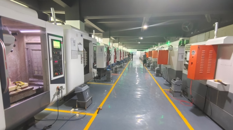
We run 16 simultaneous 5-axis machining centers alongside 12 four-axis mills and 27 three-axis machines. The choice is not prestige. A simple bracket with through-holes is faster and cheaper on 3-axis. A contoured impeller or a medical housing with angled ports is only practical on 5-axis. Matching the axis count to the geometry is the first CAM decision.
- 13-axisSimple prismatic parts, one or two setups, lowest programming cost.
- 24-axisCylindrical or multi-face parts, one datum, good for shafts.
- 35-axisContoured surfaces and angled features, rigid short tools.
What Material Does to the CAM and CNC Machine Pair
Aluminum 6061 and 7075 cut freely. CAM can push aggressive feeds, and the machine mostly worries about chip evacuation. A 12 mm three-flute cutter in 6061 might run 0.15 mm per tooth at 12,000 rpm. Surface finish lands around Ra 0.8–1.6 μm without extra effort.
Stainless 304 and 316 work-harden. If CAM leaves a light rubbing pass, the surface hardens and the next pass cuts worse. The fix is a heavier chip load, not a lighter one. This is counterintuitive and a common cause of poor stainless finishes. Toolpaths must stay engaged in the cut.
Titanium Ti-6Al-4V and Inconel push heat into the tool. CAM should favor trochoidal paths that keep radial engagement low while maintaining chip thickness. The machine needs high-pressure coolant and enough spindle torque at low rpm. Both halves of the pair are working near their limits.
Plastics like POM and PEEK behave differently again. They move with heat and can burr at the exit edge. CAM uses sharp toolpaths and climb cutting; the machine uses lower spindle speeds and generous coolant or air blast. There is no single feed-and-speed table that covers all materials.
- 1AluminumHigh speed, light rigidity demand, easy chip evacuation.
- 2StainlessKeep the cutter engaged, avoid rubbing passes.
- 3Titanium and InconelLow radial engagement, high coolant pressure, rigid setups.
- 4PlasticsSharp edges, lower speeds, watch for thermal growth.
CAM vs CNC Machine: Where Each One Owns the Result
Use this table when a defect appears and you need to know which side to fix.
| Decision | CAM software owns it | CNC machine owns it |
|---|---|---|
| Toolpath shape | Roughing and finishing strategy, stepover, order | Interpolation and blending between blocks |
| Feed and speed | Nominal values from the tool library | What the drive can hold under load |
| Corner accuracy | Chord tolerance and smoothing settings | Look-ahead, acceleration limits, following error |
| Surface finish | Stepover, lead-in, and engagement angle | Spindle runout, rigidity, chatter resistance |
| Datum strategy | Setup plan and work offset assignment | Probe repeatability and table position |
| Thermal behavior | Not modeled in most CAM packages | Spindle and ballscrew growth over a run |
| Access and reach | Stock model and holder collision check | Actual travel limits and axis geometry |
The Verdict: Fix the Right Half First
If the defect repeats on every part in the run, fix the CAM program. If it drifts or varies part to part, fix the machine setup. That single rule resolves most tolerance arguments before they start.
CAM and CNC Machine Questions
Can a CNC machine run without CAM software?
Yes. An operator can write G-code by hand or teach positions at the control. This is common for simple facing, drilling, or one-off repair work.
For contoured surfaces, undercuts, or anything with more than a few dozen tool moves, hand programming becomes slow and error-prone. CAM is the practical choice there.
Does better CAM software improve part accuracy?
It improves the toolpath, which helps. A smoother path reduces sudden direction changes and lets the machine hold speed through corners.
It cannot fix a machine with worn ballscrews or a spindle with high runout. Accuracy comes from the weaker of the two halves, not the stronger.
What tolerance can a typical CAM and CNC machine setup hold?
On a rigid setup with the right tooling, we hold ±0.005 mm on critical features. That figure comes from the machine and the fixturing, not from the software alone.
Tighter than that is possible on selected features with grinding or lapping, but it is a different process, not a CAM setting.
Why does the same G-code cut differently on two machines?
Different controls blend motion differently. Look-ahead depth, acceleration limits, and servo tuning all vary between machines, even from the same builder.
The post-processor also matters. A program posted for one control may run on another but produce rounded corners or chatter.
How long does CAM programming take for a new part?
A simple 3-axis bracket might take under an hour to program and verify. A 5-axis contoured part with tight tolerances can take a full day.
We review the CAD file during quoting and flag features that will drive programming time before the job starts.
Do you provide the CAM program with the parts?
We can supply inspection reports and process documentation on request. The CAM program itself stays with us.
We sign NDAs when a customer needs design confidentiality. Uploads are handled as confidential by default.
Send a CAD File and Get a CAM-Ready Quote
We review geometry, axis count, and tolerance before quoting, so the CAM plan and the machine are matched to your part from the start.
12-hour quote100% inspectionNDA available
More Machining Notes
We publish setup notes, tooling trials and inspection data from the factory floor.











