Systematic mechanical deviations of machine tools can be recorded by the system, but due to environmental factors such as temperature or mechanical load, deviations may still appear or increase during subsequent use. In these cases, SINUMERIK can offer different compensation functions. Use measurements obtained with real position encoders (e.g. gratings) or additional sensors (e.g. laser interferometers, etc.) to compensate for deviations and achieve better machining results. In this issue you will learn about common SINUMERIK compensation functions. Practical SINUMERIK measuring cycles such as “MOTION MEASUREMENT CYCLE996” can provide comprehensive support to end users during the continuous monitoring and maintenance of machine tools.
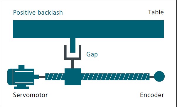
game compensation
There will be interruptions or delays in the transmission of force between the moving parts of the machine tool and its driving parts, such as ball screws, because a mechanical structure without gaps will significantly increase the wear of the machine tool , and it is also difficult to achieve technologically. Mechanical backlash causes deviations between the motion path of the axis/spindle and the measured values of the indirect measuring system. This means that once the direction is changed, the axis will move too far or too close, depending on the size of the deviation. The workbench and its associated encoder are also affected: if the position of the encoder is ahead of the workbench, the latter reaches the command position earlier, which means that the distance actually traveled by the machine tool is reduced. During machine operation, using the backlash compensation function on the corresponding axis, the previously recorded deviation will be automatically activated when reversing direction, superimposing the previously recorded deviation on the actual position value .
Lead screw pitch error compensation

The principle of indirect measurement in CNC control systems is based on the assumption that the pitch of the ball screw remains unchanged during the effective stroke. Therefore, in theory, the actual position of the linear axis can be inferred based on the motion information. of the drive motor.
However, errors in ball screw manufacturing can lead to deviations in the measuring system (also called screw pitch errors). This problem can be further aggravated by measurement deviations (depending on the measurement system used) and installation errors of the measurement system on the machine tool (also called measurement system errors). In order to compensate for these two errors, an independent measuring system (laser measurement) can be used to measure the natural error curve of the CNC machine tool, and then the required compensation value is recorded in the CNC system for compensation.
Friction compensation (quadrant error compensation) and dynamic friction compensation

Quadrant error compensation (also called friction compensation) is suitable for all of the above situations to significantly increase contour accuracy when machining round contours. Here’s why: During a quadrant transition, one axis moves at maximum feedrate, while the other axis remains stationary. Therefore, the different friction behavior of the two axes can lead to contour errors. Quadrant error compensation can effectively reduce this error and ensure excellent machining results. The density of the compensation pulses can be set according to an acceleration-dependent characteristic curve, which can be determined and parameterized by a rounding test. During the roundness test, the difference between the actual position of the circular contour and the programmed radius (especially during inversion) is recorded quantitatively and displayed graphically on the man-machine interface.
In the new version of the system software, the built-in dynamic friction compensation function can dynamically compensate according to the friction behavior of the machine tool at different speeds, reduce the actual machining contour error, and achieve control precision higher.
Compensation for sag and angle errors

If the weight of certain machine parts causes the moving parts to shift and tilt, sag compensation is necessary as this can cause the affected machine parts, including the guide system, to sag. Angle error compensation is used when the movable axes are not aligned with each other at the correct angle (e.g. vertically). As the zero point position offset increases, the position error also increases. Both errors are caused by the self-weight of the machine tool or the weight of the tool and workpiece. The compensation values measured during debugging are quantified and stored in SINUMERIK in a form, for example a compensation table, depending on the corresponding position. When the machine tool is in operation, the positions of the axes concerned are interpolated according to the stored point compensation values. For each continuous movement, there are base and compensation axes.
temperature compensation
Heat can cause parts of the machine tool to expand. The expansion range depends on temperature, thermal conductivity, etc. of each part of the machine tool. Different temperatures can cause changes in the actual position of each axis, which can negatively impact the accuracy of the part being processed. These actual value changes can be compensated for by temperature compensation. The error curves of each axis at different temperatures can be defined. In order to always correctly compensate for thermal expansion, temperature compensation values, reference position and linear gradient angle parameters must be continuously transmitted from the PLC to the CNC control system via function blocks. Unexpected changes in parameters are automatically eliminated by the control system, thus avoiding machine overload and activating monitoring functions.
Spatial Error Compensation System (VCS)

Errors in the position of rotary axes, their mutual compensation and tool orientation can lead to systematic geometric errors in components such as rotary heads and orientation heads. In addition, small errors will occur in the feed axis guiding system of each machine tool. For linear axes, these errors are linear position errors; errors in horizontal and vertical straightness and for the axes of rotation, errors in pitch, yaw and roll angle; Other errors can occur when aligning machine tool components with each other. For example, vertical error. In a three-axis machine tool, this means that 21 geometric errors can occur on the tool tip: six types of errors per linear axis multiplied by three axes, plus three angular errors. These deviations work together to form a total error, also called spatial error.
Spatial error describes the deviation of the tool center point position (TCP) of an actual machine tool from that of an ideal, error-free machine tool. SINUMERIK solution partners can determine spatial errors using laser measuring devices. Measuring the error in one place is not enough; all machine tool errors in the entire machining space must be measured. It is usually necessary to record the measured values at all positions and plot them as a curve, because the size of each error depends on the position of the relevant feed axis and the measurement position. For example, when the y and z axes are at different positions, the resulting deviation on the x axis will be different: errors will occur even at almost the same position on the x axis. With “CYCLE996 – Motion Measurement” you can determine rotary axis errors in just a few minutes. This means that the precision of the machine tool can be constantly checked and, if necessary, corrected, even during production.
Deviation compensation (dynamic feedforward control)

Deviation refers to the deviation of the position controller from the standard when the machine axis is moving. Axis deviation is the difference between the target position of the machine tool axis and its actual position. Deviations cause unnecessary speed-related contour errors, especially when the contour curvature changes, such as circular, square, etc. contours. Thanks to the advanced NC language instruction FFWON in the part program, speed-related deviations can be reduced to zero when moving along the path. Improve path accuracy with feedforward control to achieve better processing results.
FFWON: command to start anticipatory control
FFWOF: command to deactivate anticipatory control
Electronic weight compensation
In extreme cases, to prevent the axis from sagging and damaging the machine, tool or workpiece, the electronic counterweight function can be activated. In loaded axles without mechanical or hydraulic counterweights, the vertical axle may collapse unexpectedly once the brake is released. Unexpected shaft sag can be compensated for when the electronic counterweight is activated. After releasing the brake, the position of the collapsed shaft is maintained by a constant balancing torque.
Daguang focuses on providing solutions such as precision CNC machining services (3-axis, 4-axis, 5-axis machining), CNC milling, 3D printing and rapid prototyping services.


