
What Are the Advantages of CNC Return and Milling Machines in CNC?
Turned and milled features usually need two machines, two fixtures and two datums. A mill-turn or turn-mill center keeps the part in one setup. This page explains the five advantages of CNC return and milling, the tolerance and geometry limits behind them, and the part shapes where the approach stops paying off.
One workholding datum instead of two
Turning and milling are two different motions. Turning rotates the part against a single-point tool, so the geometry it produces is naturally round: diameters, faces, grooves, threads, tapers. Milling rotates the tool instead, so it can cut flats, pockets, slots and angled faces anywhere the tool can reach. Neither process replaces the other. A housing with a bored bore and a milled mounting pad needs both.
On separate machines, the part is cut on a lathe, removed, then re-clamped on a mill against a new datum. Every re-clamp adds a stacking error. If the lathe holds the bore to ±0.01 mm and the mill locates from a face that is itself 0.02 mm off, the bore-to-pad relationship can drift by 0.03 mm before any cutting error is counted.
A mill-turn center changes the order of operations, not the physics. The part is gripped once in the main spindle, turned, then the same spindle indexes and a driven tool mills the flats. The datum never changes hands. Bore-to-pad position then depends on machine geometry, which is calibrated, instead of on two fixture setups, which are not.
The advantage is largest on parts where a turned feature and a milled feature must stay concentric or square to each other. It shrinks on parts where the two features live on opposite ends and a re-clamp was never the bottleneck.
Machines in this class are not all the same. A mill-turn center starts from a lathe platform and adds rotary tooling. A turn-mill center starts from a machining center and adds a turning spindle. The first favors round parts with secondary flats. The second favors blocky parts with a few turned bores.
Bar stock, complex shapes and fewer setups
A bar-fed mill-turn center can take 3,000 mm bar, part it off, finish the back side on a sub-spindle, and drop a complete part. On a two-machine route, the same part sits in a queue twice, gets deburred twice, and is inspected twice. Setup count is where the hours actually go on small-to-medium volumes.
Fewer setups also mean fewer fixture plates, soft jaws and custom clamps. That matters for prototypes and for parts that will only ever run in the tens. Fixture design and first-article checking can take longer than the cutting on a low-volume job.
Complex shapes benefit most when the part has features on several faces. A valve body with a bore, two angled ports and a mounting flange is a natural fit because one rotary axis reaches all of them without a second op.
The route is less attractive when the part is a simple shaft with no cross features. A plain turning center with a tailstock and a steady rest will beat a mill-turn center on cycle time and on hourly rate, because you pay for axes you never index.
Thin-wall and long parts push back. Interrupted cuts on a slender tube can deflect the wall, and a driven tool pushing sideways loads the part differently than a turning tool. Support with a steady rest, take lighter radial cuts, and expect to slow the feed.
Tolerances, surface finish and in-process checks
Our mill-turn and 5-axis work is quoted at ±0.005 mm (±0.0002 in) on critical features when the geometry allows it. That figure is not automatic. It depends on material, wall thickness, tool reach and how many faces must be blended. A short, rigid, well-supported feature holds it. A deep pocket at 8 × diameter reach does not.
Surface finish follows the same logic. Turning with a sharp insert and a small nose radius reaches Ra 0.2–0.8 μm on a good day. Milled floors and walls typically land at Ra 0.8–1.6 μm, and as-machined surfaces sit at Ra 1.6–3.2 μm. Mixing the two processes on one part means the finish spec has to be written per surface, not per drawing.
In-process probing helps here. A touch probe can check a bore or a pad before the part leaves the spindle, and the offset can be corrected in the same setup. That is cheaper than scrapping a part that was 0.01 mm out after four hours of cutting.
Thermal drift is the quiet enemy. A spindle that has run for six hours is not the same machine it was at hour one. On tight work, warm up the spindle, keep the coolant steady, and probe the first few parts rather than trusting the offsets from the setup sheet.
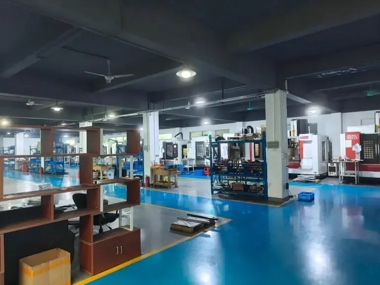
We run 127 high-precision CNC machines across three plants, including 16 simultaneous 5-axis machining centers, 12 four-axis mills, 27 three-axis machines and 16 mill-turn centers. The route is chosen per part, not by habit.
Every job ships after 100% inspection. Raw material is checked on receipt, dimensions are monitored in process, and a final inspection report can be issued on request.
Which materials and part sizes actually suit it
Aluminium is the easiest case. 6061-T6, 2024, 7075 and ADC12 all cut freely, hold tolerance well, and let a driven tool take a real chip load. If your part is an aluminium housing with a bore and cross ports, mill-turn is close to a default choice.
Stainless and steel need more care. 303 and 304 turn cleanly but work-harden if the tool rubs. 17-4PH and 4140 reward rigid setups and correct inserts. Inconel and titanium TC4 (Ti-6Al-4V) punish light radial cuts, so the driven tool spends a long time in the cut and the cycle cost climbs.
Size sets the ceiling. We can process parts up to 4,000 mm. Large travels cover 4,000 × 400 × 150 mm, mid-size machines cover 750 × 1,150 × 550 mm and 600 × 600 × 600 mm, and compact machines cover 500 × 500 × 450 mm and 500 × 310 × 200 mm. A driven-tool lathe with a Ø400 mm rotary table is the practical limit for milled features on a turned body.
Plastics behave differently. POM, PEEK, PA and ABS cut fast but move with heat. Clamp pressure can ovalize a thin POM ring before the tool touches it. Use soft jaws, light clamping and air blast rather than flood coolant.
Carbon fibre is its own problem. It is abrasive, it delaminates, and dust control matters. It can be machined, but it is not a job for a general-purpose turning cell without extraction and a fresh tool strategy.
If your part is a single prototype, no minimum order quantity applies. We run from one piece to 10,000+ part runs, so the same route can carry a design from first article to production.
When the combined route is the wrong call
Combining turning and milling is not automatically cheaper. The machine hour rate for a mill-turn center is higher than for a plain lathe, because the iron, the tooling and the programming are all more expensive. If the part has no cross features, that premium buys nothing.
Long, slender shafts are a poor fit. A shaft with a keyway can be milled on a separate mill in a few minutes, and the lathe can keep its steady rest in place. Moving that work onto a mill-turn center forces you to remove the steady rest and support the part differently.
Parts with very deep bores or narrow slots can also be a bad match. Tool reach is limited by the driven tool holder, and a long, thin end mill will chatter. Sometimes a separate sinker EDM or a dedicated milling setup is the honest answer.
High-volume simple parts are the clearest case against it. A dedicated lathe cell running one operation will beat a flexible mill-turn center on cycle time every shift. Flexibility costs seconds, and at 100,000 pieces those seconds are the whole margin.
Heat treat and finishing often split the route anyway. If a part needs hardening between operations, the datum moves regardless of how clever the first setup was. Plan the sequence before choosing the machine.
The honest test is simple. Count the features that need a second setup. If the answer is two or more, and they must stay related to a turned datum, the combined route usually wins. If the answer is zero, use a lathe.
Which route fits which part
Use this as a first filter, not as a quote.
| Part type | Best route | Why |
|---|---|---|
| Housing with bore plus cross ports | Mill-turn center | One datum keeps bore and ports related |
| Plain shaft, no cross features | Turning center | No driven-tool premium to pay |
| Block with a few turned bores | Turn-mill center | Milling platform with added turning spindle |
| Thin-wall tube, interrupted cuts | Turning center with steady rest | Side load from driven tools deflects walls |
| Deep narrow slot or bore | Separate mill or EDM | Driven-tool reach and stiffness run out |
| 100,000-piece simple part | Dedicated lathe cell | Cycle time beats flexibility at volume |
| Prototype, one piece | Either, no MOQ | Setup cost dominates, not cycle time |
The short version
If two or more milled features must stay related to a turned datum, put the part on a mill-turn center and hold ±0.005 mm in one setup. If the part is a plain shaft or a one-operation high-volume item, keep it on a lathe and spend the difference on cycle time.
Common questions
Is a mill-turn center the same as a 5-axis machine?
No. A mill-turn center is built around a turning spindle and adds rotary tooling, so its natural output is a round part with secondary milled features.
A 5-axis machining center is built around a milling spindle and adds two rotary axes to the table or the head. It is the better choice for a block-shaped part that must be cut on five faces with no turning features at all.
How tight a tolerance can a combined route hold?
We quote ±0.005 mm (±0.0002 in) on critical features when the geometry supports it. That requires a short, rigid feature, a stable material and a warm spindle.
Deep pockets, thin walls and long tool reaches loosen the practical window. In those cases the drawing tolerance may need to be opened, or the feature moved to a separate operation with better support.
What surface finish should I expect?
Turned surfaces with a sharp insert and a small nose radius typically reach Ra 0.2–0.8 μm. Milled floors and walls usually land at Ra 0.8–1.6 μm, and as-machined surfaces at Ra 1.6–3.2 μm.
Write the finish per surface on the drawing. A single blanket callout across turned and milled faces is hard to meet and hard to inspect.
Does combining operations raise the price?
The hourly rate is higher than a plain lathe, but the total can be lower because one setup replaces two. Fixture cost, queue time and re-inspection all drop.
On a part with no cross features the premium buys nothing. That is the case where a separate lathe op is genuinely cheaper.
What is the maximum part size?
We can process parts up to 4,000 mm. Large travels cover 4,000 × 400 × 150 mm and mid-size machines cover 750 × 1,150 × 550 mm or 600 × 600 × 600 mm.
Milled features on a turned body are limited by the driven-tool lathe, which carries a Ø400 mm rotary table.
Can you start from one prototype?
Yes. There is no minimum order quantity, and the same route can carry a design from a single prototype to a 10,000+ part run.
Quotation and a free DFM analysis come back within 12 hours, and production can start within 24 hours of approval. Parts normally ship in 3–5 days.
Send the drawing, get a route recommendation
Upload a STEP file and we will tell you which machine the part belongs on, with a quote and a free DFM analysis inside 12 hours.
12-hour quote100% inspectionNDA on request
More from the shop floor
We publish setup notes, tooling trials and inspection data from the factory floor.











