
CNC Machined Aluminum Accuracy: Rules That Hold on the Shop Floor
The variables that decide whether an aluminum part holds ±0.005 mm or drifts out of tolerance. Written for design engineers and buyers who need to judge a drawing before it is cut, and to know which features aluminum will not hold.
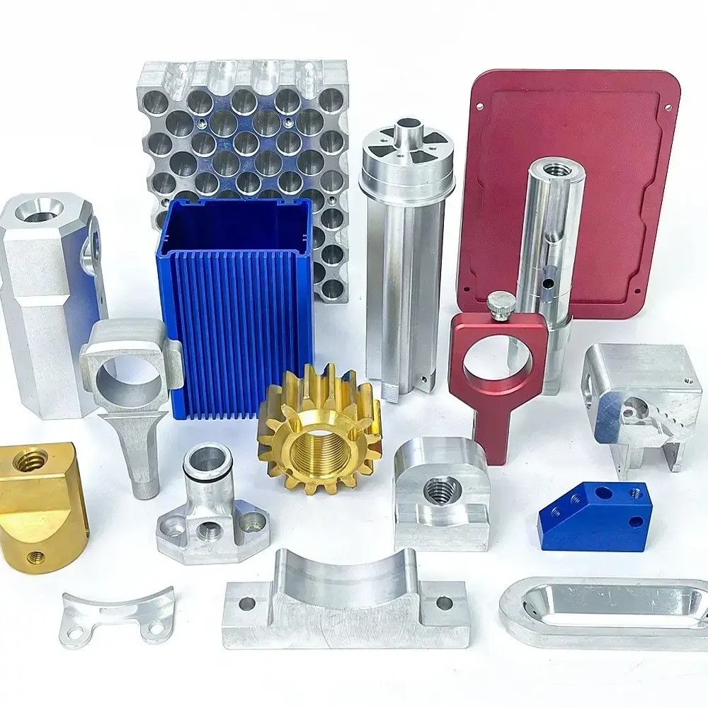
Why aluminum cuts fast and still misses tolerance
Aluminum is soft, light and machines at high spindle speeds, which makes it the default material for prototypes and enclosures. That same softness is the problem. A 6061-T6 block moves under clamping force, expands when the cutter warms it, and springs back after the tool passes.
The mechanism is straightforward. Aluminum has roughly three times the thermal expansion of steel, about 23 × 10⁻⁶ per °C. A 100 mm aluminum rib that warms by 10 °C during roughing grows about 0.023 mm. That is several times the ±0.005 mm tolerance we work to at GreatLight, so the part can be cut perfectly and still measure out of spec once it cools.
Clamping is the second source. Vise jaws tightened by hand can push 2–5 kN into a thin wall. The wall deflects while the tool cuts, then springs back to its free shape after unclamping. The measured error shows up only after the part leaves the machine.
Neither effect is visible on the screen. This is why cnc machined aluminum accuracy is decided by process control, not by the controller. The same G-code on two machines can produce two different parts if the setup and the thermal state differ.
- 1Thermal growth23 × 10⁻⁶ per °C, roughly 3× steel. Let the part cool before final cuts.
- 2Clamp deflectionThin walls move under jaw pressure and spring back after unclamping.
- 3Tool push-offAluminum deflects away from a dull or long end mill, cutting undersize.
Alloy choice sets the accuracy ceiling
Not all aluminum behaves the same at the spindle. 6061-T6 is the workhorse: stable, weldable, and consistent from lot to lot. It holds ±0.005 mm on features above 2 mm and takes a good anodized finish. For most brackets, housings and fixtures, 6061-T6 is the right call.
2024 and 7075 are stronger but less forgiving. 7075 machines cleanly and holds fine detail, yet it is more sensitive to residual stress inside the plate. Remove 60 percent of the stock from one side and the part will bow as the internal stress balances out. The bow often appears 24 hours later, after the part has been inspected and passed.
Cast alloys such as ADC12 bring porosity. A pore opened by the cutter can leave a void on a sealing face or a thread that strips at low torque. If a drawing calls for a pressure-tight surface, specify 6061-T6 bar or plate rather than a casting.
The practical rule: match the alloy to the feature, not to the whole part. Use 7075 only where strength is the driver, and expect to rough, stress-relieve, then finish.
- 16061-T6Stable, predictable, best all-round choice for tight tolerance work.
- 27075-T6Stronger, but needs roughing plus a stress-relief pause before finishing.
- 32024-T4Good fatigue behavior, more prone to distortion on thin sections.
- 4ADC12 castPorosity risk on sealing faces and fine threads.
Workholding and tool path do the real work
A part that is held badly cannot be cut well. On thin aluminum plates, we avoid heavy vise pressure and use vacuum chucks, soft jaws machined to the part profile, or sacrificial tabs. For a 2 mm wall, the finishing pass often runs with the clamp released and only light locating pins holding position.
Tool path matters just as much. Climb milling leaves a better finish and less tool pressure than conventional milling on aluminum. A high helix end mill (40–45°) clears chips fast, and chip evacuation is critical: recutting a chip at 15,000 rpm will scratch the surface and can break a small cutter.
Roughing should leave 0.3–0.5 mm of stock for finishing. Skip that and the finish pass has to remove too much, which loads the tool and pushes the part. On deep pockets, use the shortest flute length you can, because tool deflection scales with the cube of the length.
For features on multiple faces, 5-axis machining reduces the number of setups. Each re-fixture adds a fresh alignment error, often 0.01–0.03 mm. Cutting five faces in one setup removes four of those errors at once.
- 1Soft jaws or vacuumDistribute clamping load, no point pressure on thin walls.
- 2Climb millingLower cutting force, better finish on aluminum.
- 30.3–0.5 mm finish stockKeeps the finishing pass light and predictable.
- 4Fewer setupsEvery re-fixture adds 0.01–0.03 mm of alignment error.
Temperature control and the limits of measurement
A machine tool grows as it runs. Spindle and ballscrew heat can shift the tool tip by 0.02 mm over a morning of cutting. Shops that care about cnc machined aluminum accuracy either run warm-up cycles, keep the shop at 20 ± 2 °C, or measure and compensate.
Inspection has its own floor. A caliper reads to 0.02 mm on a good day and depends on the operator's touch. Micrometers and bore gauges are better for diameters. For true position or profile, a CMM is the only honest answer, and it needs its own temperature soak before measuring.
The part must be at room temperature before final inspection. Measuring a part straight off the machine gives a number that will change within the hour. We let aluminum parts stabilize, then inspect, which is why 100 percent inspection before shipment is a step and not a checkbox.
Surface finish and tolerance trade against each other. A Ra 0.2–0.8 μm finish needs a light finishing pass with a sharp tool. Push for both a mirror finish and ±0.005 mm on a deep pocket, and the cost rises fast. Sometimes Ra 1.6–3.2 μm as-machined is the smarter spec.
- 1Shop at 20 ± 2 °CReduces thermal drift between roughing and finishing.
- 2CMM for positionCalipers are not enough for true position or profile.
- 3Let parts coolInspect at room temperature, not off the machine.
- 4Finish vs toleranceRa 0.2–0.8 μm and ±0.005 mm together raise cost sharply.
When aluminum holds the tolerance, and when it does not
Match the feature to the process before you release the drawing.
| Feature | Holds ±0.005 mm? | What to do instead |
|---|---|---|
| Bores above Ø6 mm in 6061-T6 | Yes | Bore and ream in one setup after cooling. |
| Walls under 1.5 mm thick | Risky | Relax to ±0.02 mm or add ribs. |
| Deep pockets over 5× diameter | No | Use a shorter tool, accept ±0.02 mm. |
| Threads under M2 in 7075 | Marginal | Consider inserts or a larger thread. |
| Flatness over 300 mm | Depends | Specify after stress relief, not as-machined. |
| Sealing faces on cast ADC12 | No | Switch to 6061-T6 plate, then machine. |
| Position across 5 faces | Yes | One 5-axis setup beats five re-fixtures. |
The takeaway
If your part is 6061-T6 with walls above 1.5 mm, specify ±0.005 mm and let the shop control temperature and setup. If it is thin, deep, or cast, loosen the tolerance or change the design. Tolerance is a design decision, not a wish.
Questions engineers ask before releasing a drawing
What tolerance can aluminum really hold in production?
On 6061-T6 features above 2 mm, ±0.005 mm is realistic and is the standard we quote. Below 1.5 mm wall thickness, or on pockets deeper than five times the tool diameter, expect ±0.02 mm unless the design changes.
The number depends on geometry more than on the machine. A rigid part holds tight; a thin one does not, no matter how good the spindle is.
Does anodizing change the dimensions?
Yes. Type II anodizing builds roughly 5–12 μm per surface, and hardcoat can add 25–50 μm. That growth lands on every dimension the coating touches.
If a bore or shaft is tolerance-critical, mask it or machine undersize before coating. Tell the shop the finish before the final pass, not after.
Why did my part measure good at the shop and bad a day later?
Residual stress. Removing material lets internal stress rebalance, and the part bends slowly. It is common in 7075 plate and in parts where more than half the stock comes off one side.
The fix is rough machining, a pause to let the part move, then finishing. Sometimes a stress-relief heat treat between the two.
How many setups should a tight-tolerance part need?
As few as possible. Every re-fixture introduces a new alignment error, typically 0.01–0.03 mm. A part with features on five faces that runs in one 5-axis setup avoids four of those errors.
When a part must be flipped, use a machined soft jaw or a fixture keyed to the first setup so the second one references the same datum.
Is a CMM report included?
Inspection is 100 percent before shipment, covering raw material, in-process checks and final inspection. Reports are available on request.
Tell us which dimensions are critical on the drawing. We focus the inspection on those and record the numbers.
Can you work from a STEP file and flag problems?
Yes. We return a quotation and a free DFM analysis within 12 hours, listing features that will not hold tolerance as drawn and what to change.
Uploads stay confidential, and an NDA is available on request for parts that are not yet public.
Send the drawing, get a DFM review in 12 hours
We check every tight feature against the alloy, the wall thickness and the setup before quoting. Production can start within 24 hours, and parts ship in 3–5 days.
12-hour quote100% inspectionNo MOQ
More from GreatLight
We publish setup notes, tooling trials and inspection data from the factory floor.











