CNC Knowledge: There are so many ways to do CNC machining! ! !

1. Influence on cutting temperature: cutting speed, feed speed, reverse cutting quantity Influence on cutting force: quantity of countercut, feed speed, cutting speed Influence on tool durability: cutting speed, feed speed, reverse engagement 2. When the back cutting quantity is doubled, the cutting force will be doubled. When the feed is doubled, the cutting force […]

Content Navigation

1. Influence on cutting temperature: cutting speed, feed speed, reverse cutting quantity

Influence on cutting force: quantity of countercut, feed speed, cutting speed

Influence on tool durability: cutting speed, feed speed, reverse engagement

2. When the back cutting quantity is doubled, the cutting force will be doubled.

When the feed is doubled, the cutting force increases by approximately 70%

When the cutting speed doubles, the cutting force gradually decreases

In other words, if G99 is used, the cutting speed will increase, but the cutting force will not change much.

3. Based on the iron chip discharge, it can be judged that the cutting force and cutting temperature are within the normal range.

4. When the actual measured value) The R you chased may scratch the knife at the starting position.

5. The temperature represented by the color of iron filings: white is less than 200 degrees

Yellow 220-240 degrees

Dark blue 290 degrees

Blue 320-350 degrees

Purple black is above 500 degrees

Red is above 800 degrees

6. FUNAC OI mtc generally defaults to the G command:

G69: I’m not sure

G21: Metric size input

G25: Spindle speed fluctuation detection disconnected

G80: Fixed cycle cancellation

G54: default coordinate system

G18: selection of the ZX plan

G96 (G97): constant linear speed control

G99: Feed per revolution

G40: Canceling tool nose compensation (G41 G42)

G22: recorded stroke detection is activated

G67: Modal call of macro program canceled

G64: I’m not sure

G13.1: Polar coordinate interpolation mode canceled

7. The external thread is generally 1.3P and the internal thread is 1.08P.

8. S1200 thread speed/thread pitch*safety factor (generally 0.8)

9. Hand tool tip R compensation formula: chamfering from bottom to top: Z=R*(1-tan(a/2)) (a) From Just change the chamfer from least to most going up and down.

10. Every time the feed increases by 0.05, the rotation speed decreases by 50 to 80 rpm. This is because decreasing the rotational speed means that tool wear decreases and the cutting force increases more slowly, thus compensating for the increase in cut. strength and temperature due to increased power impact.

11. The influence of cutting speed and cutting force on the tool is crucial. Excessive cutting force is the main reason for tool collapse. The relationship between cutting speed and cutting force: the faster the cutting speed, the feed remains unchanged and the cutting force slowly decreases. At the same time, the faster the cutting speed, the faster the tool wears, making the cutting force larger and larger. , and the temperature will also increase. The higher it is, when the cutting force and internal stress are too great for the blade to handle (of course, there are reasons for this too, such as stress caused by temperature changes). and a reduction in hardness).

12. When processing CNC lathes, special attention should be paid to the following points:

1) At present, economical CNC lathes in my country generally use ordinary three-phase asynchronous motors to achieve stepless speed change through frequency converters. If there is no mechanical deceleration, the spindle output torque is often insufficient at low speed. too big, it’s easy to become boring. However, some machine tools are equipped with gears, which can solve this problem very well.

2) Try to ensure that the tool can finish processing a part or a shift. When finishing large parts, special attention should be paid to avoiding mid-process tool changes to ensure that the tool can be processed in one go.

3) When using CNC turning threads, use higher speed as much as possible to achieve efficient and high-quality production.

4), use G96 as much as possible

5), the basic concept of high-speed machining is to make the feed exceed the heat conduction speed, thereby discharging the cutting heat with the iron chips to isolate the cutting heat from the workpiece to be machined to ensure that the part does not heat up or heat up. Therefore, high-speed machining involves choosing a high cutting speed with high feed while selecting a smaller amount of backcut.

6), Pay attention to the tool tip compensation R

13. Workpiece material machinability classification table (small P79)

Commonly used thread cutting times and back cutting table (large P587)

Commonly used geometric calculation formulas (large P42)

Inches and millimeters conversion table (large P27)

14. Vibration and chipping often occur during grooving. The basic reasons for this are increased cutting force and insufficient tool rigidity. The shorter the tool extension, the smaller the clearance angle and the larger the blade area, the better the rigidity. cutting force, the larger the width of the grooving cutter, the cutting force it can bear will increase accordingly, but its cutting force will also increase. On the contrary, the smaller the slot cutter, the less force it can withstand, but it is. the cutting force is also low

15. Reasons for vibration during turning:

1) If the extension length of the tool is too long, the rigidity will be reduced.

2), the feed speed is too slow, which will cause the cutting force of the unit to increase and cause severe vibration. The formula is: P = F/back cutting quantity*f. P is the unit cutting force and F is the unit cutting force. cutting force. Additionally, the rotation speed is too fast. This also makes the knife vibrate.

3) The machine tool is not rigid enough, which means the cutting tool can resist the cutting force, but the machine tool cannot. To put it bluntly, the machine tool cannot move. Generally, new beds will not have this kind of problem. Beds that have this kind of problem are either very old or are often machine tool killers.

16. When sculpting a product, I found that the dimensions were good at first, but after a few hours, I found that the dimensions had changed and the dimensions were unstable. The reason may be that the knives were brand new at the beginning, so. the cutting force was too weak. It is not very large, but after rotating for a while, the tool wears out and the cutting force increases, causing the workpiece to move on the chuck, so the dimensions are often offset and unstable .

17. When using G71, the values ​​of P and Q cannot exceed the sequence number of the entire program, otherwise an alarm will appear: The G71-G73 command format is incorrect, at least in FUANC .

18. There are two subroutine formats in the FANUC system:

1) The first three digits of P000 0000 refer to the number of cycles and the last four digits correspond to the program number.

2) The first four digits of P0000L000 are the program number and the three digits after L are the number of cycles.

19. If the starting point of the arc remains unchanged and the end point is shifted by one mm in the Z direction, then the position of the lower diameter of the arc will be shifted by a/2.

20. When drilling deep holes, the drill bit does not grind the cutting groove to make it easier for the drill bit to remove chips.

21. If you are using a tool holder to drill holes for tooling, you can rotate the bit to change the diameter of the hole.

22. When drilling stainless steel center holes or stainless steel holes, the center of the drill bit or center drill bit should be small, otherwise it will not be drilled. When drilling holes with a cobalt drill bit, do not grind the groove to avoid annealing. the drill bit during the drilling process.

23. According to the process, there are generally three types of cutting: single-piece cutting, two-piece cutting and whole bar cutting.

24. When an ellipse appears when donning, the material may be loose. Just use a dental knife to clean it several times.

25. In some systems that can enter macro programs, macro programs can be used instead of subroutine loops. This can save program numbers and avoid many problems.

26. If you use a drill bit to ream the hole, but the hole has significant runout, you can use a flat bottom drill to ream the hole, but the twist drill bit should be short to increase rigidity.

27. If you directly use a drill bit to drill a hole on a drill, the diameter of the hole may differ. However, if you enlarge the hole on a drill, the size will generally not change. 10mm drill bit to enlarge the hole on the drill, the diameter of the enlarged hole will generally be the same, with a tolerance of about 3 threads.

28. When digging small holes (through holes), try to roll the chips continuously and then eject them from the tail. Key points for rolling chips: 1. The knife position should be high enough. 2. The appropriate blade tilt angle. and the amount of cutting. In addition to the feed speed, remember that the knife cannot be too low, otherwise it will be easy to break the chips. If the secondary deflection angle of the knife is large, the chips will not get stuck in the tool. bar even if the chips are broken. If the secondary deflection angle is too small, the chips will remain stuck in the tool after the chips are broken. The pole is subject to danger.

29. The larger the cross section of the tool holder in the hole, the less likely it is to vibrate. You can also tie a strong rubber band on the tool holder, as the strong rubber band can absorb vibration to some extent.

30. When turning copper holes, the R tip of the knife can be larger (R0.4-R0.8). Especially when you turn the cone, the iron parts may be thin, but the copper parts will get stuck.

Daguang focuses on providing solutions such as precision CNC machining services (3-axis, 4-axis, 5-axis machining), CNC milling, 3D printing and rapid prototyping services.

Picture of JinShui Chen

JinShui Chen

Rapid Prototyping & Rapid Manufacturing Expert

Specialize in CNC machining, 3D printing, urethane casting, rapid tooling, injection molding, metal casting, sheet metal and extrusion

Pressroom

Recent Posts

Welcome to GreatLight Metal,Maximum Processing Size 4,000 mm

Precision Machining CNC Quote Online

Loading file

Upload Click here to upload or drag and drop your model to the canvas.

The model is too large and has been resized to fit in the printer's build tray. [Hide]

The model is too large to fit in the printer's build tray. [Hide]

The model is too large, a fitting printer is selected. [Hide]

The model is too small and has been upscaled. [Hide]

Warning: The selected printer can not print in full color [Hide]

Warning: obj models with multiple meshes are not yet supported [Hide]

Warning: Unsupported DXF entity  [Hide]

Warning: could not arrange models [Hide]


File Unit:      
Scale:
%
L × W × H:
X: × Y: × Z:  cm 
Rotation:
X: ° Y: °  


Model Stats:

Material Volume: cm3
Support Material Volume: cm3
Box Volume: cm3
Surface Area: cm2
Model Weight: g
Model Dimensions:
x x cm
Number of Polygons:
Number of Shapes:
Total Path: cm
⚡ Instant Quote for Precision Manufacturing

Submit your design files (STEP/IGES/DWG) and receive a competitive quote within 1 hour, backed by ISO 9001-certified quality assurance.

📋 How It Works

  1. Upload & SpecifyShare your 3D model and select materials (Aluminum/Stainless Steel/Titanium/PEEK), tolerances (±0.002mm), and surface treatments.

  2. AI-Powered AnalysisOur system calculates optimal machining strategy and cost based on 10+ years of automotive/aerospace data.

  3. Review & ConfirmGet a detailed breakdown including:
    - Volume pricing tiers (1-10,000+ units)
    - Lead time (3-7 days standard)
    - DFM feedback for cost optimization

Unit Price: 

Loading price
5 Axis CNC Machining Equipment
4 Axis CNC Machining Equipment
3 Axis CNC Machining Equipment
CNC Milling & Turning Equipment
Prototype and Short-Run Injection Moldings Exact plastic material as final design
Volume Metal Die Casting Services - Precision Cast Parts
Bridge the Gap From Prototype to Production – Global delivery in 10 days or less
Custom high-precision sheet metal prototypes and parts, as fast as 5 days.
Custom Online 3D Printing Services
Design Best Processing Method According To 3D Drawings
Alloys Aluminum 6061, 6061-T6 Aluminum 2024 Aluminum 5052 Aluminum 5083 Aluminum 6063 Aluminum 6082 Aluminum 7075, 7075-T6 Aluminum ADC12 (A380)
Alloys Brass C27400 Brass C28000 Brass C36000
Alloys Stainless Steel SUS201 Stainless Steel SUS303 Stainless Steel SUS 304 Stainless Steel SUS316 Stainless Steel SUS316L Stainless Steel SUS420 Stainless Steel SUS430 Stainless Steel SUS431 Stainless Steel SUS440C Stainless Steel SUS630/17-4PH Stainless Steel AISI 304
Inconel718
Carbon Fiber
Tool Steel
Mold Steel
Alloys Titanium Alloy TA1 Titanium Alloy TA2 Titanium Alloy TC4/Ti-6Al 4V
Alloys Steel 1018, 1020, 1025, 1045, 1215, 4130, 4140, 4340, 5140, A36 Die steel Alloy steel Chisel tool steel Spring steel High speed steel Cold rolled steel Bearing steel SPCC
Alloys Copper C101(T2) Copper C103(T1) Copper C103(TU2) Copper C110(TU0) Beryllium Copper
Alloys Magnesium Alloy AZ31B Magnesium Alloy AZ91D
Low Carbon Steel
Alloys Magnesium Alloy AZ31B Magnesium Alloy AZ91D
ABS Beige(Natural) ABS Black ABS Black Antistatic ABS Milky White ABS+PC Black ABS+PC White
PC Black PC Transparent PC White PC Yellowish White PC+GF30 Black
PMMA Black PMMA Transparent PMMA White
PA(Nylon) Blue PA6 (Nylon)+GF15 Black PA6 (Nylon)+GF30 Black PA66 (Nylon) Beige(Natural) PA66 (Nylon) Black
PE Black PE White
PEEK Beige(Natural) PEEK Black
PP Black PP White PP+GF30 Black
HDPE Black HDPE White
HIPS Board White
LDPE White
This is a finish of applying powdered paint to the components and then baking it in an oven, which results in a stronger, more wear- and corrosion-resistant layer that is more durable than traditional painting methods.
No coating required, product’s natural color!
This is a finish of applying powdered paint to the components and then baking it in an oven, which results in a stronger, more wear- and corrosion-resistant layer that is more durable than traditional painting methods.
This finishing option with the shortest turnaround time. Parts have visible tool marks and potentially sharp edges and burrs, which can be removed upon request.
Sand blasting uses pressurized sand or other media to clean and texture the surface, creating a uniform, matte finish.
Polishing is the process of creating a smooth and shiny surface by rubbing it or by applying a chemical treatmen
A brushed finish creates a unidirectional satin texture, reducing the visibility of marks and scratches on the surface.
Anodizing increases corrosion resistance and wear properties, while allowing for color dyeing, ideal for aluminum parts.
Black oxide is a conversion coating that is used on steels to improve corrosion resistance and minimize light reflection.
Electroplating bonds a thin metal layer onto parts, improving wear resistance, corrosion resistance, and surface conductivity.
This is a finish of applying powdered paint to the components and then baking it in an oven, which results in a stronger, more wear- and corrosion-resistant layer that is more durable than traditional painting methods.
Please provide additional text description for other surface treatment requirements!
Material
Material
  • CNC Metals
    • Aluminum
    • Brass
    • Stainless steel
    • Inconel718
    • Carbon Fiber
    • Tool Steel
    • Mold Steel
    • Titanium
    • Alloy Steel
    • Copper
    • Bronze
    • Low Carbon Steel
    • Magnesium
  • CNC Plastics
    • ABS
    • PC
    • PMMA (Acrylic)
    • PA (Nylon)
    • PE
    • PEEK
    • PP
    • HDPE
    • HIPS
    • LDPE
Printer
Printer
  • CNC Metals
    • 5 Axis CNC Machining
    • 4 Axis CNC Machining
    • 3 Axis CNC Machining
    • CNC Milling & Turning
    • Rapid Tooling
    • Metal Die Casting
    • Vacuum Casting
    • Sheet Metal Fabrication
    • SLA 3D Printing
    • SLS 3D Printing
    • SLM 3D Printing
  • Rapid Prototyping
    • Design Best Processing Method According To 3D Drawings
Post-processing
Post-processing
Finalize
The world's first CNC machining center that dares to provide free samples!

Free for first product valued at less than $200. (Background check required)

precision machining cnc quote online

15 Years CNC Machining Services

When you’re ready to start your next project, simply upload your 3D CAD design files, and our engineers will get back to you with a quote as soon as possible.
Scroll to Top

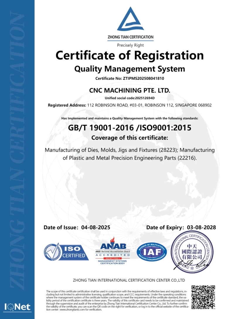
ISO 9001 Certificate

ISO 9001 is defined as the internationally recognized standard for Quality Management Systems (QMS). It is by far the most mature quality framework in the world. More than 1 million certificates were issued to organizations in 178 countries. ISO 9001 sets standards not only for the quality management system, but also for the overall management system. It helps organizations achieve success by improving customer satisfaction, employee motivation, and continuous improvement. * The ISO certificate is issued in the name of FS.com LIMITED and applied to all the products sold on FS website.

greatlight metal iso 9001 certification successfully renewed
GB T 19001-2016 IS09001-2015
✅ iso 9001:2015
greatlight metal iso 9001 certification successfully renewed zh

ISO 13485 certificate

ISO 13485 is an internationally recognized standard for Quality Management Systems (QMS) specifically tailored for the medical device industry. It outlines the requirements for organizations involved in the design, development, production, installation, and servicing of medical devices, ensuring they consistently meet regulatory requirements and customer needs. Essentially, it's a framework for medical device companies to build and maintain robust QMS processes, ultimately enhancing patient safety and device quality.

greatlight metal technology co., ltd has obtained multiple certifications (3)
greatlight metal technology co., ltd has obtained multiple certifications (4)

ISO 27001 certificate

ISO/IEC 27001 is an international standard for managing and processing information security. This standard is jointly developed by the International Organization for Standardization (ISO) and the International Electrotechnical Commission (IEC). It sets out requirements for establishing, implementing, maintaining, and continually improving an information security management system (ISMS). Ensuring the confidentiality, integrity, and availability of organizational information assets, obtaining an ISO 27001 certificate means that the enterprise has passed the audit conducted by a certification body, proving that its information security management system has met the requirements of the international standard.

greatlight metal technology co., ltd has obtained multiple certifications (1)
greatlight metal technology co., ltd has obtained multiple certifications (2)

IATF 16949 certificate

IATF 16949 is an internationally recognized Quality Management System (QMS) standard specifically for the automotive industry. It builds upon the foundation of ISO 9001 and adds specific requirements relevant to automotive production and service parts. The goal is to enhance quality, improve processes, and reduce variation and waste within the automotive supply chain.

automotive industry quality management system certification 01
automotive industry quality management system certification 00

Get The Best Price

Send drawings and detailed requirements via Email:info@glcncmachining.com
Or Fill Out The Contact Form Below:

All uploads are secure and confidential.