Small grinding head polishing. Stress disk polishing. Magnetorheological polishing.
1. Small grinding head polishing technology:
The part is polished using a grinding head much smaller than the diameter of the part. The amount of material removed is controlled by controlling the residence time of the grinding head at different locations on the workpiece surface and the pressure between the grinding head and. the workpiece.
This technology was first proposed by the American company Itek, and then gradually used in industrial manufacturing. The typical 2.4m diameter primary mirror of the Hubble Space Telescope in the United States is polished by CCOS, and the final surface precision reaches 12nm RMS.
Due to the use of computer control to replace manual experience, small grinding head technology enables optical processing to get rid of traditional manual grinding and polishing. The polishing process is stable and highly certain. Therefore, the processing efficiency and precision are also high. which can significantly shorten the processing cycle of large diameter optical components.
At the same time, small grinding head technology is simple in principle, inexpensive, easy to implement, and can be replaced with grinding heads of different sizes according to actual needs, so it has been widely used in processing large grinding heads. diameter optical components.
However, the technology of small grinding heads is still contact machining, which has some disadvantages such as edge effect, polishing disc wear and underground damage. At the same time, because the polishing disc is a rigid disc, it cannot fit well with the polishing disc. mirror surface when processing aspherical surfaces, which is easy to produce medium and high frequency errors.
2. Stress Polishing (SLP):
An aspherical surface treatment method developed based on the principle of stress deformation of thin plates. When polishing aspherical parts, the shape of the stress disk can be changed in real time to obtain the required surface shape through computer control, thereby achieving full contact between the polishing disk. and the mirrored surface of the room combine. SLP overcomes the disadvantage that the small grinding head polishing disc is a rigid disc which cannot completely adapt to the aspherical surface. This is a development and complement to small grinding head technology.
This technology was proposed in the early 1990s by the Large Mirror Laboratory at the Stiva Observatory at the University of Arizona. We have also successfully developed a stress disk polishing machine tool, which can process workpieces with a diameter of up to Φ8.0m, and the effective diameter of the stress disk is Φ1.2m. This equipment was used to process a series of large mirrors, among others. : 1.8 mf/1.0 VATT (Lennon Telescope) primary mirror, 3.5 mf/1.5 SOR primary lens, 6.5 mf/1.25 Multi-Mirror Telescope (MMT) primary lens, and primary lens 6.5 mf/1.25 Magellan primary mirror.
Compared with small grinding head technology, SLP technology is more suitable for processing large diameter optical components due to the larger strain disk diameter and high removal efficiency. When processing aspherical surfaces, the grinding head can closely fit the workpiece surface. will not produce medium and high frequency errors. However, because SLP technology, like small grinding head technology, is also a contact processing method, it also has disadvantages such as edge effects and underground damage.
In addition, when processing aspherical surfaces, the surface shape of the stress disk needs to change in real time according to the shape of the workpiece, which also requires high control technology.
3. Magnetorheological finishing technology (magnetorheological finishing, MRF):
In the early 1990s, the COM Center in the United States proposed this technology which combines electromagnetic and fluid mechanics theories and uses the rheological characteristics of magnetorheological fluid in a magnetic field to polish optical components.
MRF does not have a polishing disk and uses the shear force between the magnetorheological fluid and the workpiece to remove material. The positive pressure on the workpiece is very small, so there are no disadvantages such as polishing disc wear and underground damage during contact polishing. method.
However, due to the large size of the MRF polishing wheel, the removal efficiency is sensitive to the polishing distance, so it is not suitable for polishing very steep concave surfaces and internal cavity components of large diameter.
4. Hood polishing technology:
Use a special flexible airbag with online controllable air pressure. The shape of the airbag is a spherical crown, and a special flexible polyurethane polishing pad or polishing cloth is attached to the outside of the airbag.
This technology was proposed by the Optics Laboratory of the University of London in the 1990s to solve the problem of inconsistency between the aspherical polishing disk and the aspherical surface.
The airbag has a flexible structure and adapts well to the workpiece; the material is removed evenly in the polishing area, the process is well controllable, etc. Therefore, this method can easily process optical devices with high precision and high surface quality. In recent years, the development direction of airbag polishing technology is to improve processing efficiency, reduce edge effects, and eliminate medium and high frequency errors.
5. Ion beam calculation (IBF):
Under vacuum conditions, inert gases such as argon (Ar), krypton (Kr), and xenon (Xe) are ionized via an ion source to produce an ion beam with a certain energy that bombards the surface of the room. Reaching the surface of the part, it will exchange energy with the atoms of the part’s material. When the atoms on the surface of the part gain enough energy to escape the binding energy of the material surface, they break away from the material surface. workpiece, thus removing material.
As early as 1965, the American Meinel discovered the phenomenon of elimination of optical materials under the action of ion beams. However, the energy density of the narrow beam high-energy ion source used at the time was too high, so the mirror was unusable. burned in a short time, making it difficult to control the energy. The emission density and removal efficiency of the treatment are very low, so there has been no progress in use for a long time. It was not until the late 1970s that the emergence of the wide-beam, low-energy Kaufman ion source made this technology available. It not only limited the ion energy to the range of 300 to 1500 eV without damaging the optical mirror, but it also limited the ion energy to the range of 300 to 1500 eV. also improved the efficiency of ion beam processing, so that ion beam technology began to be formally applied to the processing of optical components.
For the above 5 types of processing equipment, please contact: 13522079385
Ion beam polishing technology has the following advantages:
Non-contact processing: During processing, the ion beam has no mechanical force on the surface of the workpiece, so it will not cause underground damage to the workpiece. At the same time, the shape and removal efficiency of the removal function will not change at the edge of the workpiece, so there is no edge effect.
High processing precision and good surface finish: processing is carried out under the precise control of computers and interferometers. In theory, the processing precision can exceed the atomic level. The treatment environment is stable, the ion beam generated by the ion source is weak. fluctuations, and there will be no wear on the surface of the part.
Gaussian suppression function: Compared with several other polishing methods, the suppression function is closest to the Gaussian distribution, which is convenient for solving the residence time distribution.
The shrinkage function has good robustness: ion beam polishing is carried out under vacuum, the shrinkage function has good controllability and stability, and is suitable for processing large diameter optical components;
Wide applicability of surface shape: During ion beam polishing, the ion beam flow is always in close contact with the workpiece surface, and there will be no medium and high frequency errors caused by the mismatch between the polishing tool and the mirror surface. it is suitable for processing spherical and aspherical surfaces, in particular. This involves high-precision machining of very stiff aspherical surfaces;
Wide range of application materials: Processing materials generally include metals, ceramics and precious stones. Typical examples include 316L stainless steel, AZI magnesium alloy, high temperature alloys, high speed steel, W6M05Cr4V2 high speed steel, composite nitride hard coating and. DLC.
To summarize:
For large diameter optical components that have high requirements for surface precision, it is always difficult to process them with high precision using a single method. Generally, different processing methods need to be combined and selected based on the amplitude distribution and frequency band. surface shape residue during the treatment process. When the residual surface shape is small and quickly approaches the target value, ion beam polishing is used for final high-precision polishing.
Judging excellent processing capabilities: a brief analysis of key processes and indicators
Above we have mentioned many relevant figures and indicators when introducing different processing technologies. Here we will briefly present some important impact indicators.
Type of treatment:
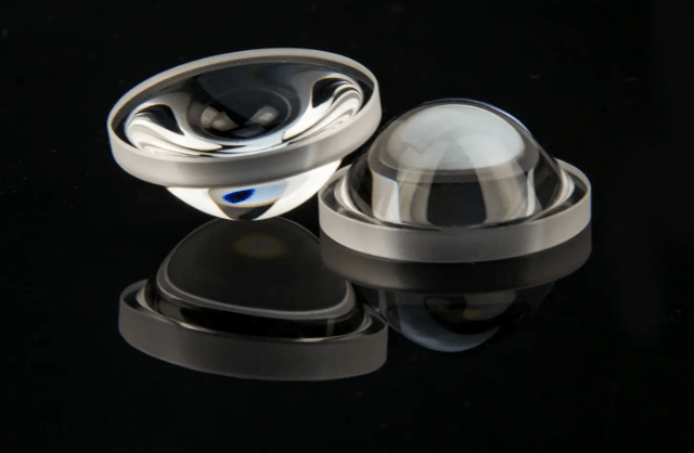
Treatment of aspherical surfaces: Generally speaking, aspherical surfaces are other surfaces excluding spheres and planes. From the application point of view, aspherical surfaces can be divided into aspherical surfaces with axial symmetry, aspherical surfaces with two symmetrical surfaces and without free symmetrical surfaces. shaped surface (spectacle lenses). The difficulty in treating aspherical surfaces is that there is no fixed and universal function expression on the surface. The spherical functions corresponding to different application scenarios may be different, which can be called free-form surfaces. the polynomial series, Zernike series or cubic spline interpolation are used to describe it, which is similar to the cumulative approximation of several small areas on the surface. This is also a limiting concept when writing a program, every point must be resolved.
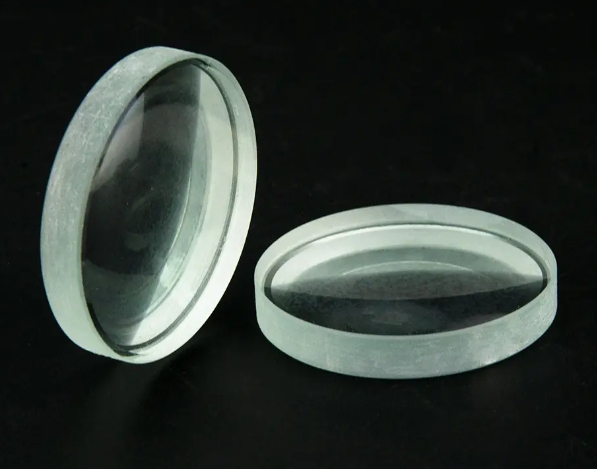
Spherical surface processing: In simple terms, the surface to be processed is a hemispherical surface or a spherical arc surface, with regular surface features, when carrying out milling, polishing and other processes, adjusting the Grinding head or polishing surface is relatively easy and can. maintain a good fit. The degree of adjustment and processing difficulty are relatively low.
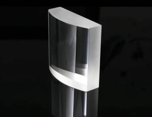
Cylindrical processing: A cylindrical mirror is a common type of aspherical lens. Its intersection with the meridional and sagittal sections is the intersection of two arcs and two parallel straight lines, respectively, if the imaging properties of the two sections are measured respectively using the spherical system. Description, one section has optical power, while the other section has no optical power When a parallel laser beam passes through the cylindrical mirror, the focus can be stretched into a line in one direction. This part of the cylindrical mirror has its specific characteristics. uses in certain specific situations. For example, it has a wide range of applications in linear detector illumination, barcode reading, holographic illumination, optical information processing, computers, laser emission, laser systems powerful synchrotron radiation beamlines.
Technical indicators:
Processing diameter: mainly for processing aspherical surfaces. Aspherical surfaces cannot be measured by the radius of a sphere or cylinder, so the diameter of the processed surface is directly used for analysis, generally ranging from mm to m. The larger the processing diameter, the larger the size of the processing surface. While ensuring certain precision requirements, the requirements for large grinding head or high-efficiency ion beam are higher. The larger the diameter, the precision remains unchanged and the processing efficiency is low; the larger the diameter, the processing efficiency is constant and the precision is low. How to ensure high efficiency and high precision in the face of large diameter or large diameter processing is an important trend and direction in optical processing.
Surface precision:
PV: Peak to Valley, PV=Wmax-Wmin. In simple terms, it is the height difference between the highest point and the lowest point of the surface to be treated (usually in µm). There are subtle differences for spherical surfaces and planar surfaces. and aspherical surfaces. Define the difference. Due to the different spatial resolutions of detectors currently used in interferometer test equipment, noise, bright spots, etc. may occur. will have a relatively large impact, so the PV is sometimes larger than the actual data, so PVr is sometimes used to describe the shape of the surface. . Precision. Regardless of the PV or PVr value, the higher the value, the rougher the surface.
RMS: root mean square, root mean square, here is its calculation formula. The formula shows that it represents an average value of all concave and convex parts of the surface. If the PV value represents the maximum height difference over the entire surface, then the RMS represents the average of all height differences over the surface. The smaller the RMS, the flatter the surface shape. Therefore, it can be seen that the lower the PV value, the higher the accuracy of the surface shape. At the same time, the RMS value must be taken into account. It’s like a fluctuating point near the mean error line.
Surface Finish: Typically, two sets of numbers are used to represent the size of defects on the surface. For example, 40/20, 40 represents the size of limited scratches on the surface and 20 represents the size of pitting defects on the surface. The smaller the two values, the higher the surface finish requirements. (Aspect ratio >4:1 is striped and aspect ratio <4:1 is pitted).
Busbar Offset: This indicator is usually listed separately in the cylindrical treatment. The cylinder can be considered as a structure formed by a plane rotating around the busbar. Busbar offset refers to the offset of one side from the center of the plane in the direction of the cylinder axis. As shown below.
To summarize:
When it comes to technical indicators, the ideal is to reach the pinnacle for each indicator. But in practice, it is a process of compatibility and compromise. For example, when facing large diameter processing, if you want to improve a certain processing efficiency, you may lose part of the processing accuracy when you want to improve it; the overall processing accuracy, it is necessary to reduce the processing efficiency to a certain extent (higher processing accuracy requires longer iterative processing times and the higher the time cost). This type of indicator requires compromises.
There is also a type of indicators that emphasize one over the other. For example, the previously mentioned PV and RMS are not the best for a single indicator. Another indicator must be able to do this. The smaller the PV value, it does not mean. that the surface is better. To some extent, the proportion of RMS is greater.
Daguang focuses on providing solutions such as precision CNC machining services (3-axis, 4-axis, 5-axis machining), CNC milling, 3D printing and rapid prototyping services.
