
RXU1000DSH High Speed Machining Center: How It Cuts
A machine-level look at what the RXU1000DSH high speed machining center does, why high spindle speeds change chip formation, and where thermal growth decides your tolerance. Written for engineers and buyers who have to justify the machine, not the brochure.
In this article
- 1
- 2
- 3
- 4
- 5
- 6
What the RXU1000DSH high speed machining center actually changes
High speed milling is not a faster version of the same cut. Once surface speed climbs past roughly 300 m/min in aluminum, most of the heat leaves with the chip instead of soaking into the part. The RXU1000DSH high speed machining center is built around that shift: a spindle that reaches high rpm without losing rigidity, and motion control that keeps the feed per tooth constant through corners.
The practical result is a cooler workpiece. On a 6061-T6 bracket with thin 2.5 mm walls, a high speed finishing pass at 18,000 rpm and 0.05 mm radial engagement keeps the wall from bowing, because the cutting force stays low and the heat never accumulates in the section. A conventional 8,000 rpm pass with a 0.5 mm radial cut pushes more heat into the same wall and the wall moves.
The machine also matters at the tool tip. Runout of 5 μm on a 12 mm end mill leaves one flute doing more work than the others, and that one flute fails first. The RXU1000DSH class of machine holds tool runout tighter because the spindle taper and the holder interface are matched and the thermal compensation keeps the spindle at a stable length.
- 1Heat partitionMost heat exits with the chip at high surface speed.
- 2Low radial engagement0.05 mm radial cuts keep side load on thin walls small.
- 3Runout controlTool runout near 5 μm spreads load evenly across flutes.
Size, swing, and the Ø895 mm treatment diameter
Swing is the first number to check. A treatment diameter up to Ø895 mm means the machine can rotate a part of that size without the table or the guard limiting the cut. For a cylindrical housing, a large flange, or a valve body, that envelope decides whether you can hold the part in one setup or need a second operation on another machine.
One setup is worth real money. Every refixture adds a datum error, and a datum error of 0.02 mm between operations has to be absorbed somewhere in the tolerance stack. If the part fits the Ø895 mm envelope and the features are reachable from one direction, you keep the whole tolerance budget on the machine instead of splitting it across two.
The boundary is stiffness, not just size. A tall, thin part at the edge of the envelope will chatter long before it runs out of travel. Fixture the part low and close to the table, support it near the top of the cut, and reduce axial depth of cut if the wall rings. A large swing rating does not remove the need for a stiff setup.
Thermal growth is the real limit on ±0.005 mm
A spindle grows as it warms. In steel, 1 °C over a 200 mm spindle shaft moves the tool tip about 2.3 μm. Over a four-hour run, a 4–6 °C rise can move the tip 10 μm or more if the machine does nothing about it. That is twice the ±0.005 mm tolerance band, and it happens without any alarm going off.
Compensation handles the repeatable part. The spindle runs through a warm-up cycle, the control reads the growth from a sensor or a model, and the Z offset shifts to follow. This is why a warm-up cycle is not optional on a high speed machine. Skip it and the first fifty parts sit at a different height than the next five hundred.
The room matters too. A 20 ±2 °C shop and a 20 ±8 °C shop behave differently on a 600 mm part. Aluminum expands about 23 μm per meter per °C. A 6 °C swing across a long part moves the measurement point roughly 83 μm by the time the part reaches the inspection room. If you need ±0.005 mm, both the machine and the metrology area have to be temperature-controlled, and the part has to stabilize before final inspection.
- 1Steel spindleAbout 2.3 μm of growth per 200 mm per °C.
- 2Warm-up cycleRun it every shift start, not only after a long stop.
- 3Aluminum partRoughly 23 μm per meter per °C of thermal expansion.
Speeds, feeds, and where the process stops working
High speed milling pays off in aluminum first. A 12 mm three-flute carbide end mill in 6061 at 18,000 rpm and 0.08 mm feed per tooth runs at about 4,300 mm/min feed. The same tool in 4140 steel runs at 2,000–3,000 rpm and 0.05 mm per tooth, closer to 400 mm/min. The machine is the same; the material sets the limit.
Titanium and Inconel are different again. Low thermal conductivity means heat stays at the cutting edge, so the answer is lower surface speed and more coolant, not more rpm. On Ti-6Al-4V, a 16 mm end mill at 60–80 m/min surface speed with high-pressure coolant through the tool is a realistic starting point. Pushing speed here burns edges.
Thin walls and long tools set the other boundary. When the tool length-to-diameter ratio passes 6:1, deflection grows fast and the finish degrades even if the spindle is capable. Reduce radial engagement, take the depth in steps, and use a tool with a relieved neck. If the part rings at 0.05 mm radial engagement, the fixture is usually the problem, not the machine.
Why a machine like this is compared to a DMU 70 class platform
The RXU1000DSH shares a working envelope with the DMU 70 class of five-axis machining centers. Buyers compare them because the parts overlap: mold inserts, housings, brackets, and small structural frames. The comparison is useful because it forces you to list what the part needs before you look at the machine.
The part list usually decides it. If the part needs five-sided access in one setup, both platforms can do it. If the part is 850 mm across and must be turned as well as milled, the larger swing matters more than spindle speed. If the part is a 40 mm aluminum connector run at 10,000 pieces a year, spindle uptime and tool life matter more than envelope.
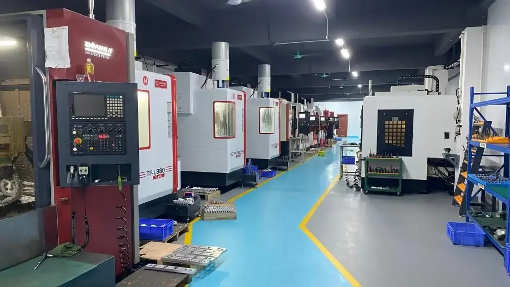
Machines are only half of a job. A capable machine with a weak fixture and no process control will not hold ±0.005 mm across a production run. We run 127 high-precision CNC machines, including 16 simultaneous 5-axis centers and 16 mill-turn centers, and we still treat fixturing and in-process inspection as the parts that decide the result.
- 1Compare envelopesMatch swing and travel to the largest feature, not the average part.
- 2Count setupsOne setup removes a datum error source.
- 3Check the fixtureMost chatter on thin parts traces back to support, not the spindle.
When high speed milling is the right process
Use this table to decide whether the part belongs on a high speed platform or a conventional one.
| Part condition | High speed platform | Conventional milling | Reason |
|---|---|---|---|
| Aluminum, thin walls under 3 mm | Yes | Risky | Low cutting force keeps walls straight |
| Hardened steel above 45 HRC | No | Yes | Edge heat shortens tool life |
| Titanium Ti-6Al-4V | Partly | Yes | Lower surface speed and more coolant |
| Large part near Ø895 mm | Yes | Limited | Swing and travel decide feasibility |
| Deep cavity, tool L/D over 8:1 | No | Yes | Tool deflection dominates the cut |
| Small parts, 10,000+ per year | Yes | Yes | Uptime and tool life drive the choice |
The decision in one line
Choose a high speed platform for aluminum and light-alloy parts with thin walls or fine detail; choose a conventional, higher-torque machine for hardened steel, titanium, and deep cavities where tool rigidity sets the limit.
Questions engineers ask next
What spindle speed range makes sense for aluminum on this class of machine?
For 6061-T6 with a 12 mm three-flute carbide tool, 15,000–20,000 rpm with 0.05–0.10 mm feed per tooth is a workable band. The exact number depends on the tool coating and the coolant delivery.
If you cannot deliver coolant to the cutting edge, drop the speed rather than the feed. Running dry at high rpm burns edges quickly.
Can the machine hold ±0.005 mm on a long production run?
The machine can, under temperature control and with a warm-up cycle. The shop has to hold both the machine and the inspection area near 20 °C, and parts must stabilize before measurement.
On a 600 mm part, a few degrees of room swing will move the measured size more than the machine error does.
Is high speed milling ever the wrong choice for aluminum?
Yes, when the part is a deep pocket with a long, small-diameter tool. Tool deflection, not spindle speed, limits the cut, and roughness gets worse as you push rpm.
Reduce engagement and step down instead. If the part still rings, the setup needs more support.
How do you check that a machine is actually cutting at the programmed feed?
Compare the commanded feed with the actual axis velocity in the control, then check the chip load by measuring the chip thickness or the surface finish. A finish that drifts mid-run usually means thermal growth or tool wear.
For tight-tolerance work, inspect the first part, a mid-run part, and the last part of the batch.
What inspection data comes with high speed machined parts?
We run 100% inspection before shipment: raw material check, in-process monitoring, and final inspection, with reports on request.
If a feature is critical, tell us the datum and the tolerance on the drawing. That is what the inspection plan is built around.
Send us the drawing and the material
We quote in 12 hours with a free DFM analysis, and parts can start production within 24 hours after release.
12-hour quote100% inspectionNo minimum order quantity
More process notes from the shop floor
We publish setup notes, tooling trials and inspection data from the factory floor.











