
5 Axis CNC High Speed Machining Technology
This page explains how simultaneous 5-axis motion and high-speed spindles work together, and what that means for part geometry, setup count and surface finish. It is written for design engineers and buyers who need to decide whether a part belongs on a 5-axis machine or on a 3-axis mill. After reading it you can judge tool access, tolerance class and the cost drivers behind a quote.
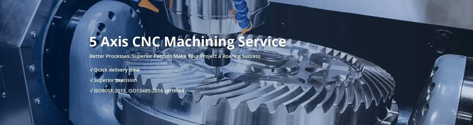
High speed is a system, not a spindle number
Five axes of motion plus a fast spindle change tool access, heat input and setup count at the same time. That combination is what makes some parts cheap and others impossible.
How simultaneous 5-axis motion changes the cut
A 3-axis mill moves the part under a spindle that stays vertical. A 5-axis machine adds two rotary axes, so the tool can tilt toward the workpiece. On the centers we run, one rotary axis is a Ø400 mm table and the other tilts the spindle or trunnion. When both rotaries move at the same time as the three linear axes, that is simultaneous 5-axis machining. The controller keeps the tool tip on the programmed path while the tool axis swings, which is why the post-processor and the machine kinematics both matter as much as the cutter.
High speed in this context means two things that are easy to confuse. First, spindle speed: small-diameter cutters in aluminium run best at high rpm, and a fast spindle keeps chip load per tooth in a workable range. Second, high-speed toolpath strategies such as trochoidal milling and constant chip-thickness control. Those paths keep radial engagement low and feed high, so heat leaves with the chip instead of soaking into the part. On thin walls and long floors, that is often the difference between a stable cut and a scrapped part.
The practical payoff is tool access. A ball-nose cutter tilted 30° can reach the floor of a deep pocket without the shank rubbing the wall. Ports, impeller blades, turbine vanes and angled bosses that would need a custom long-reach tool on a 3-axis machine can be cut with a short, stiff tool instead. Short tools chatter less, so you can hold tighter tolerances and better finish with fewer passes.
- 1Simultaneous vs 3+23+2 indexes the rotaries and cuts in a fixed orientation; simultaneous moves them through the cut.
- 2Tool axis controlTilting the cutter keeps the shank clear of the wall and lets a short tool reach deep features.
- 3Heat pathHigh feed with light radial engagement sends heat out with the chip, which limits distortion.
What the machine envelope allows
Machine size decides which parts are realistic. Our largest 5-axis travel is 4,000 × 400 × 150 mm, which suits long extrusions, rails and structural beams that need work along one dominant axis. Medium frames at 750 × 1,150 × 550 mm and 600 × 600 × 600 mm cover most housing, bracket and manifold work. Compact frames at 500 × 500 × 450 mm and 500 × 310 × 200 mm are the right home for small medical and electronics parts, where a smaller machine gives higher acceleration and better surface quality on fine detail.
The rotary table matters as much as the linear travel. A Ø400 mm table limits the swing diameter of the part; anything larger either needs a bigger platform or has to be split into operations. Fixturing also competes for space. A tombstone or trunnion fixture eats into the envelope, so the usable part size is always smaller than the brochure number. Send us the solid model with the machining datum marked and we can check reach in the CAM system before quoting.
Setup count drives cost more than spindle speed on many jobs. A part that needs five faces cut on a 3-axis machine might need three or four setups, each with its own fixture, dial-in and re-datum. On a 5-axis center the same part can often be cut in one or two setups, with the rotaries presenting each face to the tool. Fewer setups means less stack-up error, and it means the faces stay in the same coordinate system, which is where a ±0.005 mm positional tolerance across features becomes achievable.
Choosing the right machine for the part
Use this as a first filter. Real decisions depend on feature access and tolerance stack, not on part size alone.
| Part condition | Best fit | Why |
|---|---|---|
| Features on 2–3 faces, loose tolerance | 3-axis mill | Lowest hourly rate, simple fixture |
| Features on 4+ faces, one datum | 5-axis, 3+2 indexing | One setup, no re-datum error |
| Sculpted or twisted surfaces | Simultaneous 5-axis | Tool axis follows the surface normal |
| Deep pocket, long reach required | Simultaneous 5-axis | Tilted short tool avoids shank rub |
| Long beam over 1,500 mm | Large 5-axis frame | 4,000 × 400 × 150 mm travel |
| Thin wall under 1 mm | High-speed toolpaths | Light radial engagement limits deflection |
| One-off prototype, simple shape | 3-axis or 3+2 | Programming time outweighs setup savings |
Speeds, feeds and the limits of going fast
Higher rpm is not automatically better. Small cutters need high spindle speed to keep surface speed in range, but the same speed on a long tool with a large overhang will chatter. The rule we use is to match tool diameter, overhang and material first, then set the speed. Aluminium alloys such as 6061-T6 and 7075 run at high surface speed with generous feed per tooth. Titanium TC4 (Ti-6Al-4V) and Inconel run far slower, with more coolant and lower engagement, because the heat does not leave the cut as easily.
Radial engagement is the lever that matters most on high-speed paths. Dropping radial depth from 50% of cutter diameter to 10% lets you raise feed per tooth substantially while keeping the chip load constant. The cutter stays cooler and the cutting force drops, which is exactly what thin ribs and floors need. Axial depth can then go deeper, so the same volume of metal comes off in fewer passes even though each pass looks gentle.
There is a ceiling. Very high spindle speed on a part with poor fixturing just moves the vibration to a different frequency. We check setup rigidity before pushing parameters. For hard materials and interrupted cuts, a 5-axis machine with a slower spindle and a rigid trunnion will out-produce a fast spindle on a light frame every time. The technology is a set of trade-offs, not a single setting.
What accuracy and finish to expect
Our standard machining tolerance is ±0.005 mm (±0.0002 in) on critical features. That number only holds when the datum is clean, the fixture is rigid and the feature is reachable with a short tool. A deep bore at the end of a long overhang will not hold that class, and it is better to know that at the DFM stage than after the first article. For general features we work to the drawing, and we flag anything that needs a tighter class or a special process.
Surface finish follows the same logic. As-machined surfaces sit around Ra 1.6–3.2 μm. High-speed finishing paths with a small stepover reach Ra 0.8–1.6 μm, and fine finishing with the right cutter and parameters gets to Ra 0.2–0.8 μm. If a sealing face or a bearing seat needs a specific Ra, put it on the drawing with the area marked. Polishing, bead blasting and anodizing change the surface, so specify the finish after those steps, not before.
Inspection backs the claim. We check raw material on receipt, monitor in process and inspect 100% of parts before shipment, with reports available on request. For 5-axis work the first article is the important one, because it proves the setup and the post-processor at the same time. Once that is signed off, the rotary positions repeat and the rest of the run follows.
Which materials reward 5-axis high speed
Aluminium is the natural fit. Grades 6061, 6061-T6, 2024, 5052, 5083, 6063, 6082, 7075 and ADC12 all cut cleanly at high spindle speed, and the light cutting forces suit thin walls. Aerospace brackets, EV housings and heat sinks are common examples. Stainless grades 303, 304, 316, 316L, 420, 430, 431, 440C and 17-4PH (SUS630) need more attention: 303 and 316L machine well, while 17-4PH in the aged condition is harder on the cutter and benefits from a rigid setup.
Titanium and nickel alloys are where the process earns its cost. TA1, TA2, TC4 (Ti-6Al-4V), Inconel and magnesium AZ31B or AZ91D all have low thermal conductivity, so heat stays in the cut zone. Tilting the tool to keep engagement low, and using high-pressure coolant, keeps the edge alive. Copper and brass grades C101, C103, C110, beryllium copper, C27400, C28000 and C36000 cut freely but can be gummy, so chip evacuation and feed per tooth need watching.
Plastics are a different problem. ABS, PC, PMMA, POM, PA, PEEK, PP, HDPE and carbon fibre all machine on the same centers, but they need sharp tools, higher surface speed and low clamping force. Carbon fibre adds abrasive wear on the cutter. For any of these, tell us the material condition, not just the grade name, because temper and heat treatment change the cutting data more than the alloy number does.
Questions engineers ask
When is 5-axis worth it over 3-axis?
It pays off when a part has features on four or more faces, or when the tool cannot reach a feature without a long, flexible cutter. Cutting those faces in one setup removes re-datum error and usually removes a fixture.
For a simple part with features on two faces, 3-axis is cheaper. Programming and setup time on the 5-axis center will not be recovered.
Does high-speed machining mean a faster delivery?
Not directly. It shortens cycle time on complex parts and reduces the number of setups, which helps. Our quotation and free DFM analysis come back within 12 hours, production can start within 24 hours, and parts ship in 3–5 days.
The bigger schedule risk on 5-axis work is first-article approval. Get the drawing and datum settled early.
What part size can you machine?
The maximum processing size is 4,000 mm, with a large-frame travel of 4,000 × 400 × 150 mm. Medium frames cover 750 × 1,150 × 550 mm and 600 × 600 × 600 mm, and compact frames cover 500 × 500 × 450 mm and 500 × 310 × 200 mm.
Rotary table diameter is Ø400 mm. Fixtures reduce the usable envelope, so send the model for a reach check.
How do you hold ±0.005 mm on a 5-axis part?
By keeping the tool short, the setup rigid and the datum consistent across features. Cutting most faces in one setup removes the stack-up that comes from re-clamping.
We inspect 100% of parts before shipment and can supply reports. Features that cannot hold that class are flagged during DFM review.
Can you work from a 3-axis program or an STL?
We prefer a native solid model with tolerances and datums marked. A 3-axis program does not carry the tool-axis information a 5-axis machine needs, so it has to be reprogrammed.
An STL is workable for simple geometry but loses feature intent. STEP or Parasolid files cut the DFM time.
What about confidentiality and small quantities?
Uploads are secure and confidential, and an NDA is available on request. There is no minimum order quantity, so a single prototype and a 10,000+ part run both fit the same process.
For one-off parts we still run a first-article check before shipping.
Send the model and we will check reach, setup and tolerance
Upload your files for a quotation and free DFM analysis within 12 hours. Uploads stay confidential, and an NDA is available on request.
12-hour quote±0.005 mm100% inspectionNo MOQ









