
Rapid Prototyping for Quick Turning to CNC Processing
This page explains how a turned prototype moves from CAD file to finished metal part, and what the machine is doing while it cuts. It is written for design engineers and buyers who need to judge whether a turned part suits their geometry, tolerance and finish before they send a drawing out.
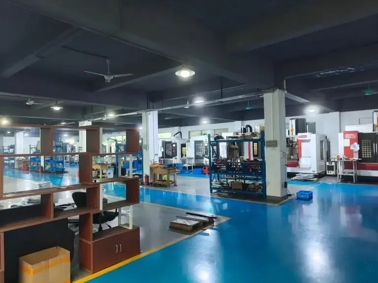
How rapid prototyping for quick turning is actually cut
Rapid prototyping for quick turning starts with one rotating workpiece and one stationary cutting tool. The spindle clamps the bar or blank and spins it at a set surface speed. The tool feeds along the Z axis, parallel to the spindle, or along the X axis, across the diameter, and peels off material as a continuous chip. Every diameter, shoulder and groove is a programmed tool path, not a hand decision.
The part that changes between prototyping and production is not the cutting principle. It is how fast you get a program, a setup and a first article. A turned prototype often comes off a bar in one or two operations, while the same part in a 10,000-piece run may move to a mill-turn center or a bar feeder with a different workholding plan.
Material removal is the whole story. Nothing is sintered, molded or glued, so the mechanical properties of the prototype match the production part as long as the alloy and heat treatment match. That is the main reason engineers pick turning over 3D printing for functional tests: a 6061-T6 bracket cut on a lathe behaves like a 6061-T6 bracket in the field.
Keep the chip load in mind when you review a quote. A light finishing pass at 0.05 mm depth leaves a different surface than a roughing pass at 1.5 mm. If your drawing calls for Ra 0.8–1.6 μm, the shop has to plan a separate finishing pass, and that adds a tool change and a few minutes of cycle time.
- 1Rotating work, fixed toolDiameter accuracy comes from spindle and slide motion, not from the tool profile alone.
- 2One setup, many featuresTurned parts can carry threads, grooves and chamfers without re-clamping.
Which turned geometries fit this route
Parts with rotational symmetry are the natural fit: shafts, bushings, spacers, pins, nozzles, valve bodies, sensor housings, connector shells and threaded adapters. If a single axis passes through most of the part, turning will be the cheapest and fastest way to make the first functional sample.
Off-axis features change the plan. Cross holes, side slots and milled flats need a second operation, a live tool, or a mill-turn center. That is still within the same process family, but it adds setup time and one more tolerance stack between the turned diameter and the milled feature. Tell the shop which of the two datums drives the fit.
Very long, slender parts are the hard case. A shaft with a 12:1 length-to-diameter ratio will deflect under cutting force, so the shop needs a steady rest, a lower feed rate, or a lighter depth of cut. Expect the price to reflect that. A 4,000 mm maximum processing size is available, but stiffness, not travel, sets the practical limit.
Thin-wall tubes and rings are the second hard case. Wall thickness below about 1 mm on a 50 mm diameter part tends to chatter and spring back after clamping. If the design allows a thicker wall in the prototype and a machined relief later, the first article will come out closer to nominal.
- 1Good fitShafts, sleeves, fittings, housings with one dominant axis.
- 2Needs a second opCross holes, milled flats, keyways, side ports.
- 3Watch the ratioBeyond roughly 10:1, expect a steady rest and slower cuts.
Tolerance, finish and what drives the cost
Turning holds ±0.005 mm on a well-supported diameter when the machine, the tool and the temperature are stable. Not every feature needs that number. Put a tight tolerance only on the surfaces that locate, seal or bear load, and leave the rest at the general block tolerance. This single habit removes more cost from a quote than any material swap.
Surface finish follows the same logic. Ra 0.2–0.8 μm is a lapped or fine-turned surface, usually reserved for seal faces and sliding fits. Ra 0.8–1.6 μm is the normal fine-turned range for mating surfaces. Ra 1.6–3.2 μm is fine for clearance bores, brackets and covers. Specify the finish per surface, not for the whole drawing.
Setup count is the hidden cost driver. A part cut in one operation with one chucking is quick. A part that needs a soft jaw, an angle fixture and a second op can double the shop time even when the cycle itself is short. If you can add a clamping boss or a flat that the shop can hold, do it.
Material choice moves the numbers too. Free-machining brass and 6061 aluminium cut fast and leave a good finish. 316L stainless work-hardens, so the shop runs lower surface speed and takes more passes. Titanium and Inconel are slower again. None of these are refused; they just change the schedule.
- 1Tight only where it mattersReserve ±0.005 mm for locating and sealing diameters.
- 2Finish per surfaceCall out Ra on the face that seals, not on the whole part.
- 3Fewer chuckingsOne setup usually beats a tighter tolerance on a second op.
From first article to a 10,000-part run
A prototype and a production run share the same cutting physics but not the same economics. For one to fifty pieces, the shop programs, sets up and inspects each part closely. For larger volumes, the same geometry moves to a bar feeder, a dedicated fixture or a mill-turn center so the cycle time drops.
The handoff point depends on the part. Simple round parts with no secondary features can run unattended at volume with almost no change. Parts with cross holes or tight angular relationships usually need a fixture before volume makes sense, because manual indexing at 5,000 pieces is both slow and inconsistent.
Inspection scales differently from cutting. A first article gets a full dimensional report. A production lot gets sampling plus in-process monitoring, with raw material checks at the front and a final inspection before shipment. Reports are available on request, which matters for aerospace, medical and automotive programs.
There is no minimum order quantity here, so a single prototype and a 10,000-part run sit on the same line. That removes the usual argument about whether a design is worth tooling up for. You test the turned part first, then decide about volume with real data.
- 1Same process, different setupVolume changes workholding and cycle time, not the cutting method.
- 2Fixture before volumeCross holes and angular features need a fixture to stay consistent.
Turning compared with other prototyping routes
Pick the route by function, not by habit.
| Route | Typical use | Tolerance | Watch out for |
|---|---|---|---|
| CNC turning | Shafts, sleeves, fittings, round housings | ±0.005 mm | Off-axis features need a second op |
| CNC milling | Plates, brackets, pockets, square bodies | ±0.005 mm | Deep pockets need long, thin tools |
| 5-axis machining | Complex angles, one-setup parts | ±0.005 mm | Higher hourly rate than 3-axis |
| 3D printing | Form and fit checks, no load | ±0.1 mm and up | Anisotropic strength, weak threads |
| Vacuum casting | Small batches of urethane parts | ±0.1 mm and up | Master pattern wear over runs |
When to turn, when to mill
If the part has one dominant axis and carries a seal, bearing or thread, turn it. If the load path runs through flat faces, pockets or angular walls, mill it. When both are present in one part, use a mill-turn center rather than splitting the part in two.
Questions engineers ask before sending a drawing
How fast can a turned prototype ship?
Quotation and a free DFM analysis come back within 12 hours. Production can start within 24 hours of approval, and parts typically ship in 3–5 days.
The clock starts when the drawing, material and finish are all confirmed. A missing thread callout or an unclear datum will hold the schedule until it is resolved.
Can a turned part also have milled features?
Yes. Cross holes, flats, slots and keyways are cut on a mill-turn center or in a second operation on a 4-axis mill.
The engineering question is which datum controls the fit. If the milled feature locates against the turned diameter, that relationship has to be called out on the drawing.
What materials are available for turning?
Aluminium grades include 6061, 6061-T6, 2024, 5052, 5083, 6063, 6082, 7075 and ADC12. Stainless covers 303, 304, 316, 316L, 420, 430, 431, 440C and 17-4PH.
Steel, brass, copper, titanium, Inconel and engineering plastics such as POM, PEEK and PA are also cut. Material choice mainly changes surface speed and cycle time.
How is a turned prototype inspected?
Raw material is checked on receipt, dimensions are monitored during cutting, and every part gets a final inspection before shipment.
Dimensional reports and material certificates are available on request. For regulated programs, the inspection plan is agreed before the first cut.
Do I need to release my design to get a quote?
Uploads are treated as secure and confidential. An NDA is available on request if your program requires one.
For an initial DFM review, a STEP file plus a PDF of the critical dimensions is usually enough. We flag features that will be slow or risky to cut.
When should the prototype not be turned?
Skip turning when the part is mostly a flat plate, when the wall is under about 1 mm on a large diameter, or when the shape has no usable axis of rotation.
In those cases milling, sheet metal or die casting will be cheaper and more stable. We will say so in the DFM note rather than quote a part that will fight the process.
Send a turned design and get a DFM note back
Upload a STEP file and we return a quote with a free DFM analysis within 12 hours.
12-hour quote100% inspectionNo MOQ
More process notes from the shop floor
We publish setup notes, tooling trials and inspection data from the factory floor.











