
Rapid Prototyping CNC Processing: Enhanced Product Design
Rapid prototyping CNC processing cuts a functional part from solid stock, so you can fit it, load it, and measure it before committing to tooling. This page explains how the process works, where its limits sit, and when a machined prototype is the wrong call.
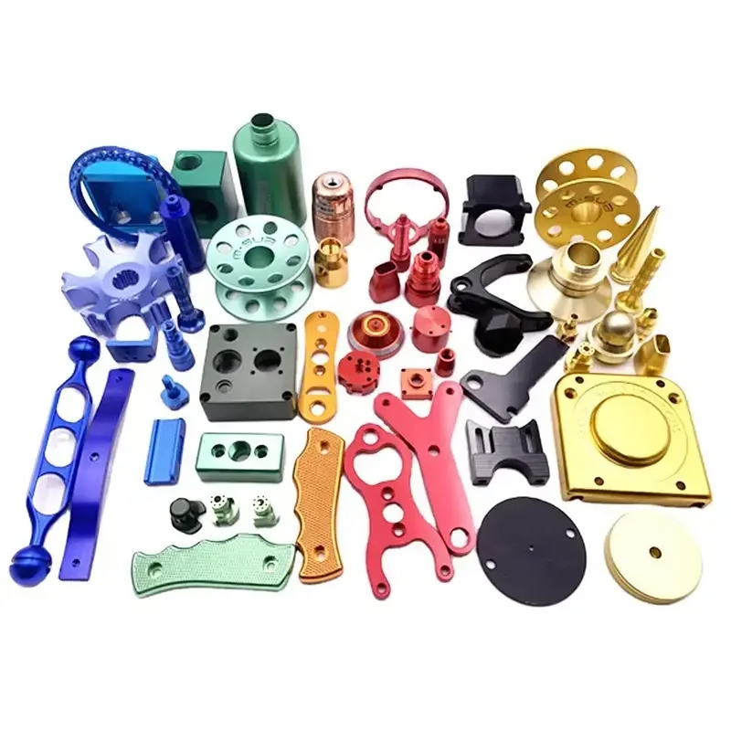
In this article
- 1
- 2
- 3
- 4
- 5
- 6
- 7
How rapid prototyping CNC processing turns a CAD model into a real part
The workflow starts with a 3D model and a material callout. We read the geometry, pick stock, and write toolpaths that cut from the outside in. The part is not built up layer by layer; it is subtracted from a solid block, so the finished prototype carries the same grain structure and density as the production part.
That difference matters during design review. A machined prototype can be torqued, pressed, dropped, and heat-cycled. Threads hold. Bearing bores stay round. You can assemble it with the real fasteners and the real mating parts, then measure the stack-up with a caliper instead of trusting a tolerance stack in the model.
Rapid prototyping CNC processing also closes the loop on features that look fine on screen but fail in metal. A 1 mm wall may vibrate during a machining pass. A deep pocket may need a tool that cannot reach the corner radius you drew. Catching those details at the prototype stage costs a toolpath change, not a mold rework.
Typical materials for this stage are 6061-T6 aluminium, 304 or 316L stainless, 17-4PH, and engineering plastics such as POM, PEEK, and PC. Each one cuts differently, and the choice usually follows the function you are testing rather than the final production material.
- 1Subtractive, not additiveMaterial is removed from solid stock, so properties match the production intent.
- 2Fit and function testingReal threads, real bores, real fasteners; measure the assembly, not the model.
- 3Fast path to a physical partProduction can start within 24 hours; parts ship in 3–5 days.
What tolerance and surface finish you can hold on a prototype
On a 5-axis machine, we hold ±0.005 mm (±0.0002 in) on critical features when the geometry supports it. That number is not a blanket promise for every dimension on the print. It applies to datumed features measured on a CMM or a surface plate, with the part fixtured the way it was machined.
Tolerance depends on the feature. A bored hole in aluminium holds tighter than a thin wall in the same part. Deep pockets deflect. Long unsupported sections spring back after the vise releases. When a drawing pushes everything to the tightest class, the honest answer is that some dimensions drive cost and time without helping function.
Surface finish follows the same logic. As-machined surfaces land around Ra 1.6–3.2 μm, which is fine for brackets, housings, and internal structure. A high finish of Ra 0.8–1.6 μm suits sealing faces and sliding contact. For optical or fluid-contact surfaces, we can reach Ra 0.2–0.8 μm with additional passes or a polishing step.
If your prototype is going into a test rig, tell us which dimensions carry the load and which are cosmetic. We will spend the tolerance budget where it changes the test result and leave the rest at a sensible shop default.
3-axis, 4-axis, and 5-axis: picking the right setup for the design
A 3-axis mill cuts from one direction. It is the cheapest and fastest option for plates, brackets, and parts with features on a single face. If your prototype is a flat mounting plate with a few holes and a pocket, there is no reason to put it on a 5-axis machine.
A 4-axis mill adds rotation around one axis, so you can cut features on multiple faces without re-fixturing. Shafts, cylindrical housings, and parts with radial bolt patterns fit here. The gain is accuracy: every face is cut in the same setup, so the relationship between features stays tight.
A 5-axis machine adds two rotary axes and lets the tool approach the part from almost any angle. Undercuts, compound angles, deep cavities, and contoured surfaces that would need three or four separate setups on a 3-axis machine get cut in one. That reduces the chance of stacking setup errors.
The rule we use: if one setup can reach every feature, stay 3-axis. If the part has features on four sides, go 4-axis. If the geometry has undercuts, compound angles, or tolerances that span five faces, use 5-axis. The machine choice should follow the drawing, not the other way around.
Where rapid prototyping CNC processing changes the design cycle
The value shows up in the second and third revision, not the first. A prototype that arrives in 3–5 days lets you run a fit check this week and send a revised model back next week. Each loop costs a toolpath edit rather than a new mold, so you can afford more loops before the design freezes.
Design teams often use the machined prototype to settle arguments that CAD cannot. Does the connector seat by hand or does it need a tool? Does the cable route clear the housing at full travel? Does the assembly fit when the parts are anodized, which adds a few micrometres per surface? These answers come from holding the part.
There is a second benefit that is easy to miss. A machined prototype can accept the production surface finish. Anodizing, bead blasting, and laser marking all behave differently on a real metal surface than on a printed one, so the sample you show to a customer or a regulator is representative.
We keep the prototype and the production run on the same inspection routine. Raw material is checked on arrival, dimensions are monitored in process, and every part is inspected before shipment. Reports are available on request, which matters when the prototype becomes the reference sample.
When a machined prototype is the wrong choice
Machining is poor at hollow, thin-wall, lattice, or organic shapes. A topology-optimized bracket with 0.8 mm walls and internal voids will chatter or distort on the table. If the geometry is defined by material removal, CNC fits. If it is defined by material addition, printing usually wins.
It is also the wrong tool when you need hundreds of identical parts in a soft plastic with a molded surface. That is vacuum casting or a bridge tool, not a machining job. Machining can make the master pattern, but the copies should come from a casting process.
Extreme aspect ratios are another limit. A hole 10× deeper than its diameter needs a specialty drill and often a wire EDM or gun-drilling step. We will quote it if the geometry allows, but expect the cost and lead time to reflect the difficulty.
Finally, machining does not replace a production process that behaves differently. A machined aluminium part is not a die-cast part. If the final process is die casting, the prototype should be made to the casting's draft angles and wall thickness, or the fit test will mislead you.
Material and finishing choices that keep the prototype honest
Pick the material by the property under test. If you are checking stiffness, 6061-T6 or 7075 gives a predictable modulus. If you are checking corrosion or a medical contact surface, 316L or 17-4PH is the closer match. If you are checking snap-fit behavior, POM or PC tells you more than aluminium ever will.
Titanium grades such as TC4 (Ti-6Al-4V) and superalloys like Inconel are available, but they cut slowly and cost more. Use them when the prototype must survive a thermal or load environment that aluminium cannot, not as a default.
Finishing should follow the production intent. Anodizing changes dimensions slightly, so a prototype that will be hardcoat anodized should be machined to the pre-finish size. Laser marking has a minimum character height of 1.5 mm, which is worth knowing before you design a serial number onto a small face.
If the prototype only needs to prove fit, skip the finish. A bead-blasted, anodized sample is worth it when the part goes in front of a customer, a test engineer, or a regulatory reviewer.
Which rapid prototyping process fits your design
Choose by geometry, tolerance, and how close the prototype must match production.
| Process | Best for | Tolerance / finish | Watch out for |
|---|---|---|---|
| 3-axis CNC | Plates, brackets, single-face parts | ±0.005 mm; Ra 1.6–3.2 μm | Multiple setups add stack-up error |
| 4-axis CNC | Shafts, housings, radial features | ±0.005 mm; Ra 0.8–1.6 μm | Limited undercut access |
| 5-axis CNC | Undercuts, compound angles, contoured faces | ±0.005 mm; Ra 0.8–1.6 μm | Higher programming cost |
| CNC turning / mill-turn | Round parts, threaded bodies | ±0.005 mm; Ra 0.8–1.6 μm | Off-axis holes need a second op |
| 3D printing | Early form checks, complex lattices | Layer lines; looser tolerance | Weak threads, anisotropic strength |
| Vacuum casting | Small runs of a molded look | Good surface; softer material | Not for functional load testing |
The short version
Choose rapid prototyping CNC processing when the prototype must carry load, hold a thread, or match production material and finish. Choose 3D printing when the shape is organic or hollow and the tolerance is loose. If the geometry is ambiguous, send the model and we will tell you which route is cheaper.
Rapid prototyping CNC processing questions engineers ask
How fast can a machined prototype ship?
Quotation and a free DFM analysis come back within 12 hours. Production can start within 24 hours of approval, and parts ship in 3–5 days. Complex 5-axis work or specialty alloys can take longer, and we will say so in the quote.
Can you hold ±0.005 mm on a prototype?
Yes, on datumed features that the setup and material support. Very thin walls, deep pockets, and long unsupported sections will deflect, so we flag those in the DFM review and suggest a realistic callout for each feature.
Do you have a minimum order quantity?
No minimum. We run from one prototype to 10,000+ part runs on the same equipment and inspection routine, so the prototype and the production part are made the same way.
Will you sign an NDA before I send the model?
Yes. Uploads are secure and confidential, and an NDA is available on request. We can sign your document or provide ours before the CAD file changes hands.
What certifications cover the prototype work?
The plants hold ISO 9001:2015, IATF 16949:2016, ISO 13485:2016, and ISO 27001:2022. Every part is inspected before shipment, with raw material checks, in-process monitoring, and final inspection reports on request.
Can the prototype use the production surface finish?
Anodizing, plating, powder coating, bead blasting, and laser marking are all available on prototypes. Tell us the final finish at quoting so we machine to the pre-finish dimension where the coating adds thickness.
Send the model and get a DFM review with the quote
Upload your CAD file and we will return a quotation plus a free DFM analysis within 12 hours, with the machining route and any tolerance risks called out.
12-hour quote100% inspectionNo MOQNDA on request
More from the shop floor
We publish setup notes, tooling trials and inspection data from the factory floor.











