
Humanoid Robot Magnesium Alloy Die Casting
Why magnesium becomes the default frame material for legged robots, and where the process turns difficult. Written for mechanical engineers and sourcing leads who must judge wall thickness, porosity and machining allowances before committing to tooling.
In this article
- 1
- 2
- 3
- 4
- 5
- 6
- 7
Why Magnesium Wins on a Walking Machine
A humanoid robot is a mass problem before it is a control problem. Every kilogram in the lower limb has to be accelerated and braked roughly once per step, so mass at the hip costs far more torque than the same mass in the torso. Magnesium alloy die casting fits that constraint better than aluminium because the density is about 1.8 g/cm³ against 2.7 g/cm³. On a joint housing that is a 30 percent weight cut for the same envelope.
The second benefit is damping. Magnesium absorbs vibration better than aluminium, which matters on a frame that carries inertial measurement units and joint encoders. Less ringing in the structure means cleaner sensor signals and less positional drift after a hard foot strike.
Neither property is free. Magnesium has a hexagonal close-packed crystal structure, so cold formability is poor and machined chips are flammable if not managed. High-pressure die casting (HPDC) is the practical route for thin-wall, net-shape parts, and it is where most of the process risk lives.
- 1Density 1.8 g/cm³Roughly 65 percent of aluminium, direct actuator torque savings.
- 2Better dampingHelps IMU and encoder stability on impact-heavy gaits.
- 3Poor cold formingRules out deep drawing; HPDC or machining only.
Which Magnesium Alloy Fits Which Robot Part
AZ91D is the general-purpose choice. It casts well, gives good strength at room temperature and is widely available. Use it for hip yokes, shoulder brackets and battery enclosures where stiffness matters more than elongation.
AM60 trades some strength for ductility. If a part sees bending loads or impact, such as a foot plate or a shin section that can hit an obstacle, the higher elongation reduces the chance of a brittle crack. It is the safer default for anything below the knee.
For high-temperature regions near actuators, standard AZ91D creeps. Rare-earth grades such as AE44 hold bolted-joint preload better at 150 °C and above. Where magnesium is not available in the required grade, AZ31B sheet or extrusion is an option for covers and brackets that do not need a casting.
- 1AZ91DBest castability and strength; hip, shoulder, enclosures.
- 2AM60More ductile; foot plates and impact-prone links.
- 3AE44 typeCreep resistance near hot actuator mounts.
Thin-Wall Flow and Porosity in Magnesium HPDC
Humanoid limbs want walls between 1.0 mm and 2.5 mm. In that range the melt can freeze before it fills the far end of the cavity, producing cold shuts. The fix is gate design and fill speed, not brute force. A short fill time keeps the metal moving, but pushing velocity too high turns the flow turbulent and entraps gas.
Gas porosity is the main defect. A 0.5 mm pore inside a 2 mm wall removes a quarter of the section, and that is where a fatigue crack starts after a few million gait cycles. Vacuum-assisted die casting pulls the cavity down during fill and reduces entrapped gas, at the cost of more tooling complexity and slower cycle time.
Shrinkage porosity is a separate problem. Thick bosses and rib intersections cool last and pull metal from the surrounding wall. Designers should keep wall transitions gradual and avoid isolated thick sections that no riser can feed.
- 1Cold shutsMelt freezes before fill completes; fix gate and fill time.
- 2Gas porosityTurbulent fill traps air; vacuum assist helps.
- 3ShrinkageThick bosses starve thin walls; blend transitions.
Machining Allowances After the Casting Drops
A casting is a near-net shape, not a finished part. Datum faces, bearing bores and actuator mounting pads usually need machining. Add 0.3–0.5 mm of stock on faces that will be cut, and keep cast draft on surfaces that stay as-cast. Casting tolerance typically sits around ±0.1 mm on stable dimensions and looser across parting lines, so do not design a bearing fit directly into a cast bore.
Magnesium machines fast. Cutting speeds can run higher than aluminium, and tool life is good, but fine chips ignite easily. Dry machining with proper extraction, or a controlled oil mist, is standard. Never use water-based coolant on magnesium; the reaction produces hydrogen.
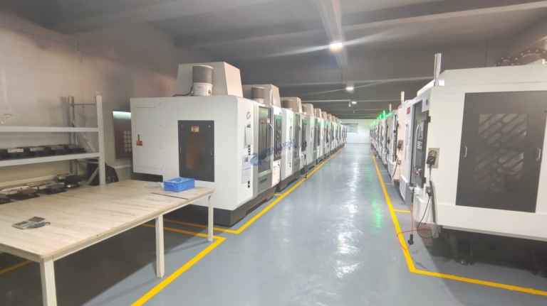
GreatLight runs magnesium as part of a wider metal program, so a cast frame can move straight to 5-axis trimming, boring and finishing without a second supplier. That matters most on joint housings where the cast datum and the machined bore have to agree.
- 1Stock allowance0.3–0.5 mm on machined faces; draft on as-cast.
- 2No water coolantHydrogen risk; use oil mist or dry with extraction.
- 3Bores need machiningCasting tolerance is too loose for bearing fits.
Boundary Conditions: When Casting Is the Wrong Answer
Below a few hundred parts per year, tooling amortisation dominates. A CNC billet frame has a higher unit price but no mould cost, and it can be revised between builds. For a robot in pilot production, that flexibility is usually worth more than the per-part savings.
Very thick sections are also a poor fit. If a design needs a 12 mm solid boss for a high-load bearing, the casting will cool slowly and shrink. A machined insert or a hybrid design with a steel or aluminium insert cast in place often works better.
Tolerance is the third boundary. Casting alone will not hold ±0.005 mm. If the drawing calls for tight coaxiality between two bores, plan a machining operation after casting and budget the fixture cost.
- 1Low volumeUnder a few hundred parts, billet machining wins.
- 2Thick solid sectionsShrinkage risk; consider inserts or hybrids.
- 3Tight coaxialityCast then machine; never cast to ±0.005 mm.
Cost Structure and the Path to Volume
The cost of a magnesium frame splits into tooling, casting cycle, machining and finishing. Tooling is a one-time hit that scales with part size and slide count. Cycle time is driven by wall thickness: thinner walls fill faster but need higher injection pressure and a more capable machine.
Machining cost tracks the number of setups and the tight-tolerance features. A part that needs five faces machined on a 5-axis centre is more expensive than one that needs two. Designers can cut cost by consolidating datums and keeping tight tolerances only where the function demands them.
Finishing is usually anodising or a conversion coating for corrosion protection, plus laser marking for traceability. Magnesium needs a specific treatment; standard aluminium anodising lines will not run it. Plan that step early rather than after the first batch.
- 1ToolingScales with size and slide count, one-time cost.
- 2MachiningTracks setups and tight-tolerance features.
- 3FinishingMagnesium needs its own coating line.
Magnesium Alloy Die Casting vs the Alternatives
Use this to pick a route before you commit to tooling.
| Route | Best for | Wall thickness | Tooling / unit cost |
|---|---|---|---|
| Magnesium HPDC | Thin-wall frames at volume | 1.0–2.5 mm | High tooling, low unit |
| Aluminium HPDC | Stiff parts, less weight pressure | 1.5–3.0 mm | High tooling, low unit |
| CNC from billet | Prototypes and low volume | 0.8 mm and up | No tooling, high unit |
| Magnesium HPDC + CNC | Bearing bores and datums | 1.0–2.5 mm | Tooling plus machining |
| AZ31B sheet | Covers and flat brackets | 0.8–3.0 mm | Low tooling, medium unit |
The Practical Verdict
If you are past a few hundred units and the part is a thin-wall structural frame, magnesium alloy die casting is the right route: pick AZ91D for stiffness, AM60 for impact zones, then machine the bores. If you are still in pilot builds, machine from billet and defer tooling until the geometry stops changing.
Questions Engineers Ask Before Tooling
What is the minimum wall thickness for magnesium alloy die casting?
Around 1.0 mm is achievable on small parts with a well-designed gate and a capable machine, but 1.5–2.0 mm is a safer production band. Below 1.0 mm the melt tends to freeze before the cavity fills, and porosity risk rises sharply.
Can a magnesium casting hold ±0.005 mm without machining?
No. Casting tolerance is typically around ±0.1 mm on stable dimensions and looser across parting lines. The ±0.005 mm figure applies to CNC machining after the casting, on surfaces that are actually cut.
How does magnesium compare with aluminium for a robot frame?
Magnesium is about a third lighter for the same volume and damps vibration better. Aluminium is cheaper per kilogram, easier to weld and less reactive in the foundry. For legged robots the weight and damping usually decide it.
Is magnesium flammable during machining?
Fine chips can ignite. The rule is no water-based coolant, controlled chip extraction and dry or oil-mist cutting. With those controls in place magnesium machines cleanly at high speed with good tool life.
What surface finish can I expect on a cast magnesium part?
As-cast surfaces sit around Ra 1.6–3.2 μm depending on the mould. Machined faces can reach Ra 0.8–1.6 μm, and finer at Ra 0.2–0.8 μm where the function needs it. Corrosion protection is a separate coating step.
Do I need a vacuum-assisted die casting machine?
It depends on the part. Vacuum assist reduces gas porosity and helps on large, thin-wall frames or parts with long flow paths. On simple, thicker brackets a conventional machine is often sufficient and cycles faster.
Send Us the Frame Drawing
Upload a STEP file and we will return a quotation with a free DFM analysis within 12 hours, covering wall thickness, draft, machining stock and gate position.
12-hour quoteFree DFM analysis100% inspectionNo minimum order quantity
More From the Shop Floor
We publish setup notes, tooling trials and inspection data from the factory floor.











