
Robot LED Indicator Housings Die Casting
A housing that holds an LED window is a thermal part, an optical part and a sealing part at the same time. This page explains how robot led indicator housings die casting actually works, where the process wins, where it loses to machining or molding, and which checks decide the outcome.
In this article
- 1
- 2
- 3
- 4
- 5
- 6
What Makes Robot LED Indicator Housings Die Casting Demanding
An indicator housing looks like a small box with a hole. In service it does three jobs at once: it pulls heat out of the LED board, it holds a window in a known position, and it keeps dust and coolant away from the electronics behind it. Those three jobs pull the design in different directions.
Heat is the first constraint. A status LED running at 1 W inside a closed housing will lift the junction temperature well above ambient if there is no metal path. Die cast aluminium carries heat away because the alloy itself conducts roughly 120–180 W/m·K, and because the casting can be shaped into a thick boss right under the board.
The second constraint is optical. The window sits in a machined pocket, so the pocket floor decides where light lands. A 0.2 mm step in that floor is invisible on a drawing and obvious on a robot arm at night. Flatness and position matter more than surface gloss.
The third constraint is the seal. A gasket groove that is 0.15 mm too shallow will still assemble and still pass a visual check. It fails six months later in a washdown cell. Tolerances on sealing features are the ones worth spending machining time on.
Alloy Choice and Wall Thickness in Die Cast Housings
ADC12 and A380 cover most robot indicator work. Both flow well, both take a machined thread, and both are easy to source in Asia and Europe. ADC12 has slightly better castability and is the common choice for thin cosmetic walls. A380 is a little tougher and machines with a cleaner chip.
Wall thickness is where most first articles go wrong. A 1.5 mm nominal wall fills reliably on a 3,000 kN machine. Push to 1.0 mm over a large area and you will see cold shuts at the far end of the cavity. Design at 2.0–3.0 mm for structural ribs and 1.5–2.5 mm for cosmetic surfaces.
Thick sections are the opposite problem. A 6 mm boss next to a 2 mm wall cools at a different rate and pulls porosity toward the thick side. Keep bosses under about 1.5 times the nominal wall, or core them out and machine the bore afterwards.
Aluminium also forms its own oxide layer, which is why these housings survive humid warehouses and outdoor AGV routes without extra coating. Anodizing adds hardness and colour, but it does not fix a porous casting underneath.
Why CNC Post-Processing Decides the Finished Part
Die casting gets you 90 percent of the geometry in one shot. It does not get you the 10 percent that touches anything else. As-cast tolerance on a typical aluminium housing sits around ±0.1 mm at best and drifts with die wear, so every interface surface needs a machining pass.
The window pocket is the first operation. Face it, then mill the pocket floor in one continuous pass so there is no tool mark step. A Ø6 mm or Ø8 mm end mill at 8,000–12,000 rpm leaves Ra 0.8–1.6 μm in aluminium without a separate polishing step.
Mounting holes and threads come next. Threads in die cast aluminium are weaker than threads in 6061, so they get a machined pilot and a formed or cut thread with full engagement. If the screw is removed often during service, plan on a thread insert.
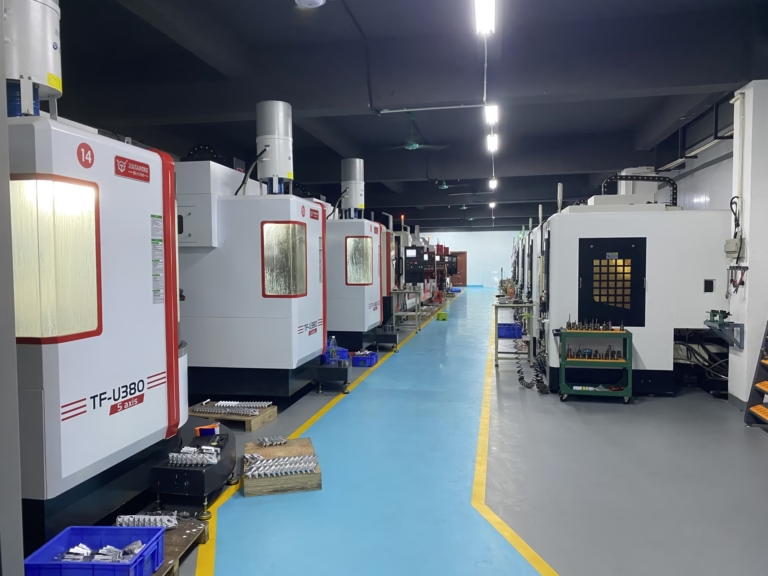
Connector cutouts and gasket grooves are the tightest features. Those are where ±0.005 mm capability actually earns its place, and where a shop that only does casting will hand the part to a subcontractor and lose a week.
Design Rules for Casting, Machining and Light
Design for castability first. Draft 1–2° on all vertical faces, fillets of at least 0.5 mm at internal corners, and no undercuts that need a side action. Every side action adds tooling cost and a parting line you then have to hide.
Design for machining second. Leave 0.3–0.5 mm of stock on any surface that will be cut. Do not ask for a machined face on a surface the tool cannot reach without a long, thin end mill; the chatter will show on the window edge.
Design for light third. Keep the LED board on a flat boss with a defined contact area, not on three cast pads. Add a light barrier between adjacent indicators if two colours sit close together, otherwise the red bleeds into the green at the operator's viewing angle.
Finally, plan the finish before the tool is cut. A bead-blasted surface hides die lines and small porosity. A polished surface exposes both. If the housing is visible on a cobot arm, bead blast plus clear anodize is the lower-risk route.
Where the Hidden Cost Sits
The visible cost is the part price. The hidden cost is rework. A housing that needs the window pocket re-cut after anodizing costs more than the original machining, because the anodized skin has to be broken and re-finished.
Porosity is the second hidden cost. A 0.3 mm pore under the window shows up as a dark speck when the LED is lit. X-ray on the first article is cheaper than sorting 5,000 parts by hand.
Die wear is the third. A tool run hard will drift out of tolerance near the end of its life, and the last 20 percent of the order carries the risk. Ask for in-process monitoring rather than a final inspection only.
None of these are reasons to avoid casting. They are reasons to pick a supplier who machines and casts under one roof, so the tolerance chain has one owner.
Four Ways to Make an LED Indicator Housing
Volumes assume a housing up to 120 mm across.
| Process | Best volume | Typical tolerance | Where it fails |
|---|---|---|---|
| Die casting + CNC | 1,000–100,000+ | ±0.05 mm, ±0.005 mm machined | Tooling cost, 4–8 week lead |
| Plastic injection molding | 5,000+ | ±0.1 mm | No heat path, poor EMI |
| Full CNC from solid | 1–2,000 | ±0.005 mm | Unit cost at volume |
| Sheet metal fabrication | 100–5,000 | ±0.2 mm | Sealing, complex 3D shape |
When Die Casting Is the Right Call
Choose robot led indicator housings die casting when you need 1,000 pieces or more, a metal heat path and a sealed window in one part. Stay with full CNC machining below roughly 500 pieces, or when the housing changes every few weeks and tooling cannot be amortised.
Frequently Asked Questions
What alloy should we specify for an LED indicator housing?
ADC12 for thin cosmetic walls and complex fill, A380 when the housing has machined threads and structural ribs. Both conduct heat well enough for a 1–3 W indicator board. If corrosion resistance matters more than cost, ask about an aluminium alloy closer to A360 or a coating.
Can the window pocket be left as-cast?
No, if the LED has to sit in a defined position. As-cast surfaces carry draft and a parting line, and the floor will not be flat enough for a bonded window. Plan one facing pass on the pocket floor and one on the mating face.
If the window is a separate molded lens held by a bezel and position is not critical, an as-cast pocket can work at lower volumes.
How do we keep light from bleeding between two indicators?
Add a cast or machined rib between the two light paths, at least 1 mm tall above the board surface, and keep the rib in contact with the window. Painting the interior black also helps, but a physical barrier is what actually stops the bleed.
What surface finish should we ask for?
Ra 0.8–1.6 μm on sealing faces and gasket grooves, Ra 1.6–3.2 μm on general exterior surfaces. A finer finish on the exterior is usually wasted unless the housing is a visible cosmetic part on a cobot.
How do we check a casting before it is machined?
Ask for an X-ray or dye penetrant check on the first article, focused on the window boss and the gasket groove. Both features are thin and both are where porosity turns into a light leak or a seal failure.
Does anodizing change the machined dimensions?
Yes slightly. Type II clear anodize builds roughly 5–15 μm per surface, hardcoat more. If a bore or thread is tolerance-critical, mask it or allow for the build-up in the drawing.
Send the Drawing, Get a Casting and Machining Plan
Upload a STEP file and we come back with a DFM note, alloy recommendation and a quote within 12 hours.
12-hour quote100% inspectionNo minimum order
More Process Notes
We publish setup notes, tooling trials and inspection data from the factory floor.











