
How to Use CNC to Process the Brass Tap
A shop-floor guide for engineers and buyers who need brass tap bodies, spindles, and handles machined to size. We cover the five operations in order, the cutting data that keeps brass from tearing, and the checks that catch a bad thread before it ships.
Key takeaways
What a brass tap is and why it suits CNC
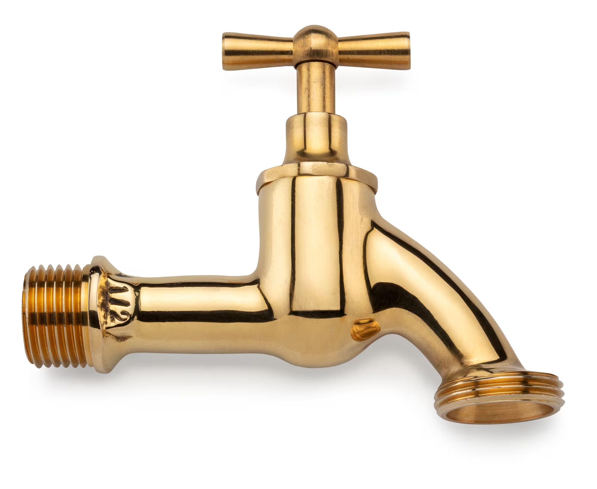
A brass tap is a valve body that controls water flow: a machined body, a rotating spindle, a seat, a threaded inlet and outlet, and a handle on top. Residential and commercial fittings both use the same basic layout. The tolerances that matter are the bore-to-spindle clearance, the seat angle, and the thread pitch diameter.
Brass is the reason this part is a good fit for CNC. C36000 free-cutting brass machines at 200–400 m/min surface speed with carbide tooling, produces short broken chips, and needs no coolant on many jobs. It also holds a fine finish straight off the tool, so a decorative tap body often needs polishing rather than heavy secondary work.
The trade-off is cost and weight. C36000 contains lead, which limits it in some potable-water markets, and the material price tracks copper. When a customer needs a lower lead content, we move to C27400 or C28000 and expect slightly shorter tool life, more stringy chips, and a small drop in surface finish quality.
CNC fits the tap because the geometry repeats. Every unit needs the same bore diameter, the same thread depth, and the same seat angle. On a lathe with a bar feeder, that repetition is where the process earns its money.
Machines and workholding for tap bodies
Most brass tap bodies under Ø60 mm run on a mill-turn center or a turning center with live tooling. We hold 16 mill-turn centers and 27 three-axis machines, so a family of tap sizes can be split across a lathe for the round features and a mill for the ports and flats.
Workholding decides the result more than the program does. For a body with a hex or square section, use soft jaws bored to the actual blank size rather than a standard three-jaw chuck. For a casting, hold on the as-cast surface with a collet or a custom fixture, and mark the parting line so the operator loads every part the same way.
For the second setup, grip the finished bore on a mandrel or an expanding collet. This keeps the thread concentric with the bore, which is what the customer feels when they turn the handle. Gripping the outside of the body instead lets the wall thickness error shift the axis.
Keep the part close to the chuck. Brass is stiff, but a tap body with a long inlet spigot will still ring and chatter if it hangs 4× its diameter out of the jaws. Support long spigots with a tailstock or a steady rest.
Speeds, feeds, and the mistakes that scrap parts
Rough the outside at 250–350 m/min with a 0.8 mm nose radius insert, 0.15–0.25 mm/rev feed, and 1.5–2.5 mm depth of cut. Finish at 400–500 m/min with a 0.4 mm nose radius and 0.05–0.08 mm/rev. That combination lands around Ra 0.8–1.6 μm, which usually passes a visual check without polishing.
Drill the bore at 80–120 m/min with through-coolant if the drill is longer than 5× diameter. Peck every 1× diameter on deep bores. Brass chips are small and heavy, and they pack into a blind hole fast. If the drill squeals, the feed is too light, not too heavy. Push it.
The most common mistake is running brass like steel. Too low a surface speed work-hardens nothing, but it rubs, and the tool edge picks up material. The second mistake is a light finishing feed on a form tool, which smears the seat instead of cutting it.
For threads, use a single-form or full-form thread mill on any wall under 3 mm. A cutting tap on M12 × 1.5 in a thin wall will push the wall out and crack it at the root. Thread mill at 150–200 m/min, and take two passes on coarse pitches.
Deburring, surface finish, and what we measure
After machining, the tap goes through tumbling or hand deburring at the thread entry, the seat edge, and every cross-drilled port. A brass burr at the thread start will cross-thread on assembly. A burr at the seat will hold the valve open by a few microns and drip.
For appearance parts, we polish or brush the body, then plate or coat. Options that work on brass include electroless nickel, silver and gold plating, powder coating, bead blasting, and laser marking with a minimum character height of 1.5 mm. Clear lacquer is common on polished bodies that stay indoors.
Inspection covers the bore diameter, the seat angle, the thread pitch diameter with a go/no-go gauge, and the concentricity of the spindle bore to the body thread. We run 100% inspection before shipment: raw material check, in-process monitoring, and final inspection, with reports on request.
Our general tolerance is ±0.005 mm and fine finishes run Ra 0.2–0.8 μm when the drawing calls for them. Those numbers only hold if the fixture is rigid and the part is deburred before it reaches the gauge.
Step by step: process the brass tap
- 11. Review the drawing and pick the datumSet the primary datum on the body bore or the mounting face, not on a cast surface. Flag every feature that controls flow: bore Ø, seat angle, thread pitch diameter, and port positions. If the drawing gives a general tolerance only, agree on the critical few before programming.
- 22. Program both setups in CAMUse one work offset for setup 1 and a second for setup 2, both referenced to the same datum. Simulate the thread mill path and check for a full thread form at the entry. Add a 0.2 mm chamfer at every thread start.
- 33. Prepare and stress-relieve the blankSaw bar stock 2–3 mm over finished length. For castings, check the first article for porosity at the seat before running the batch. Confirm the alloy against the certificate: C36000 for general work, C27400 or C28000 where lead content is restricted.
- 44. Rough and finish the first sideFace and turn the OD at 250–350 m/min roughing, 400–500 m/min finishing. Drill and bore to leave 0.1–0.2 mm for the finish pass. Break the outer edges with a 0.5 mm × 45° chamfer so the part loads cleanly in setup 2.
- 55. Flip the part and hold on the boreGrip the finished bore with an expanding collet or a bored soft jaw. Face to length, then thread mill at 150–200 m/min. Use a go/no-go gauge on the first part, not the tenth.
- 66. Cross-drill and mill the portsSpot every port before drilling. Use a stub drill at 80–120 m/min and deburr both sides of each hole. A burr on the inside of a port changes the flow curve more than a 0.05 mm hole size error.
- 77. Deburr, finish, and inspectTumble or hand deburr, then polish or plate as specified. Measure the bore, seat angle, thread pitch diameter, and concentricity. Log the readings. Ship only after the final inspection pass.
Which machining choice fits which tap
Pick the row that matches your part, not the machine you happen to have free.
| Part condition | Recommended method | Why |
|---|---|---|
| Wall under 3 mm at the thread | Thread milling, single form | Low radial force, no cracked wall |
| Thread on a solid boss over Ø20 mm | Cutting tap or thread mill | Both work; tap is faster on rigid parts |
| Cast body with as-cast ports | 3-axis mill plus soft jaws | Locates on the casting, tolerates draft |
| Tight concentricity bore to thread | Mill-turn, one datum | No re-chuck error between features |
| Polished decorative body | Turn at 400–500 m/min, then polish | Tool finish close to final; less polishing |
| Lead-restricted potable water use | C27400 or C28000, slower speeds | Lower lead, shorter tool life, more stringy chips |
Questions engineers ask before quoting
What tolerance can you hold on a brass tap body?
Our general machining tolerance is ±0.005 mm (±0.0002 in). On brass this is realistic for the bore, the seat, and the thread pitch diameter, provided the part is held on a rigid fixture and deburred before gauging.
If a feature is cosmetic or non-sealing, loosening it to ±0.05 mm usually cuts cycle time without hurting function. Tell us which dimensions actually control flow.
Can you machine a brass tap from a casting instead of bar stock?
Yes. We hold castings on the as-cast surface with soft jaws or a collet and mark the parting line so every load is consistent. The first article gets checked for porosity at the seat before the batch runs.
Castings usually need one extra finishing pass at the seat because the skin is harder than the interior.
How do you stop a thin-wall brass thread from cracking?
Switch from a cutting tap to a single-form thread mill and cut in two passes on coarse pitches. A tap pushes material outward, and a 2 mm wall will crack at the thread root.
A 0.2 mm chamfer at the thread entry also removes the sharp edge that starts the crack.
What surface finishes are available on brass?
As-machined brass comes off the tool at Ra 1.6–3.2 μm. A controlled finish pass gets Ra 0.8–1.6 μm, and fine work reaches Ra 0.2–0.8 μm.
For appearance, we offer polishing, brushing, bead blasting, electroless nickel, silver and gold plating, powder coating, and laser marking at a minimum character height of 1.5 mm.
What is the lead time and minimum order quantity?
We quote with a free DFM analysis within 12 hours, production can start within 24 hours, and parts ship in 3–5 days. There is no minimum order quantity: one prototype or a 10,000+ part run.
Uploads are secure and confidential, and we sign an NDA on request.
Do you supply inspection reports with the parts?
Yes, on request. We inspect 100% before shipment, covering raw material check, in-process monitoring, and final inspection.
Typical report data includes bore diameter, seat angle, thread pitch diameter from a go/no-go gauge, and concentricity readings.
Send the drawing, get a process plan
Upload your brass tap drawing and we return a quote with a free DFM analysis within 12 hours, plus the setup and tooling plan we would run.
12-hour quote100% inspectionNo MOQ
More from GreatLight
We publish setup notes, tooling trials and inspection data from the factory floor.











