In the process of multi-axis machining and five-axis machining, setting the origin of the workpiece coordinate system and the tool length is an important step. If the origin of the workpiece coordinate system and the tool length are set incorrectly, it will cause a tool collision accident, damage the equipment, and the consequences will be disastrous. Therefore, correctly setting the workpiece coordinate system origin and tool length is the first step to ensure safe production. Regarding this issue, there is currently a lack of relevant discussion in textbooks and literature. In particular, in many literatures on “tool setting” of three-axis CNC machine tools, the Z direction value in the G54 memory of the workpiece coordinate system. is mixed with tool length data and is not strictly distinguished. It is not advisable to use a five-axis linkage machine tool with the thought of a three-axis CNC milling machine. Therefore, detailed research and discussion will be conducted below.
In the actual operation of CNC machine tools, to set the workpiece coordinate system and tool length data, you must first understand the concepts of machine tool coordinate system and coordinate system of the room.
Machine tool coordinates are inherent to the machine tool itself and are the only coordinates that can be recognized by the machine tool’s CNC system, while workpiece coordinates are artificial and the machine- CNC tool itself cannot recognize the coordinates of the workpiece.
The essence of the principle of setting the origin of the workpiece coordinate system in a CNC machine tool is to find the value of the origin of the workpiece coordinate system in the machine tool coordinate system and store it in the memory of G54 or G56, G57. , G58, G59 and other instructions. The finding process comes from the fact that many people use cutters as tools to find them, so this process is called “tool setting.”
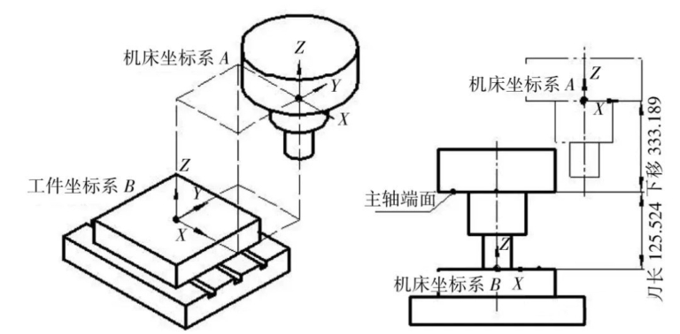
For example, in Figure 1, point A is the origin of the coordinate system of the machine tool of the CNC milling machine or machining center, and point B is the origin of the workpiece coordinate system . For point B, it has a reading value in the coordinate system of machine tool A. Suppose this value is (X-368.756 Y-367.543 Z-432.843), store this set of values in the memory of , Y, Z in the workpiece coordinate system command G54 or G55, G56, G57, G58, G59, then when executing these instructions, the machine tool will call the values in the X, Y and Z instruction memory to identify the coordinates of the part.
Figure 1 reveals the relationship between the Z value of the workpiece coordinate system origin, the tool length and the machine tool coordinate system origin, which will be explained in detail below .
First of all, you should know that in CNC milling machines and machining centers, tool length refers to the distance from the spindle end to the tool tip, and that the value is always positive. The tool length in the schematic diagram in Figure 1 is 125.524.
As shown in Figure 1, it is known that the origin A of the machine tool coordinate system is at the positive limit position of the three linear axes X, Y and Z, and the origin B of the coordinate system of the room is in the center. of the upper surface of the square piece. Find the tool length and workpiece coordinates. System B is the coordinate system value of machine tool A.
Figure 1 The relationship between the origin of the machine tool coordinate system, the Z value of the origin of the workpiece coordinate system and the length of the tool
In this schematic diagram, “125.524” is the tool length and “-333.189” is the machine’s Z coordinate system reading when the tool cuts just to the top surface of the part. It can be read directly on the screen. of the machine tool, then the value of point B of the workpiece coordinate system. The value of the Z direction value in the coordinate system of machine tool A is:
“-458.713” is stored in Z direction memory in G54 or G56, G57, G58 and G59.
“125.524” is stored in the tool length compensation register and called with “G43 H_”.
Many technicians who operate three-axis CNC milling machines regard “-333.189” as the original Z value of the workpiece coordinate system when setting tools, enter it into the G54 command Z memory, and enter “0 ” in the “H” address of the tool length compensator. In three-axis CNC machine tools, there is another storage method, which is to enter “0” in Z of the G54 command and “-333.189” in the “H” address of the tool length compensator .
These two methods will not affect the position of the tool tip when calling the “G43 H_” instruction, and the position of the tool tip in the Z axis direction is correctly determined. Because in a three-axis CNC milling machine, since there are no rotation axes such as A, B and C, the Z axis is always in a straight state. This storage method does not and will not affect the position of the tool tip. cause tool collision accident. However, in multi-axis machining machine tools and five-axis linkage CNC machine tools, the Z value “-458.713” and tool length “125.524” need to be stored separately and cannot be mixed and grasped like three-axis machine tools, otherwise A, B, C and other rotation axes may occur when linking with the Z axis, and the tool tip tracking function RTCP cannot be performed.
For safety reasons, first measure the tool length, the Z value of the coordinate system of workpiece B in the coordinate system of machine tool A, and finally measure the X and Y values.
3.1 Measure tool length
To measure the length of the tool, two points must be measured. The first point is the end face of the spindle and the second point is the tip of the tool. To measure tool length, you can use a dial gauge, Z-axis adjuster, external tool presetter, etc. It can be measured outside the machine or inside the machine. Off-machine measurement does not take machine tool time and can improve productivity, but it will increase the cost of the off-machine presetter. On-machine measurement takes machine tool usage time and productivity is lower than off-machine measurement, but there is no need to add additional instruments.
3.1.1 Pressing the pin end
As shown in Figure 2, the method of measuring tool length using a dial indicator inside the machine is used. Gently press the dial indicator probe onto the end face of the spindle, let the pointer slowly rotate a small semi-circle, and stop at the “40” position. At this point, find the “relatively real” z coordinate on the machine tool control panel and clear it. The result is shown in Figure 4. For safety reasons and to avoid interference with the tool, you can remove the tool before measuring the end face of the pin before this step.

Figure 2 Using a Dial Indicator to Measure the Pin End Face

Figure 3 Using a Dial Indicator to Measure the Tool Tip

Figure 4 After measuring the end face of the spindle with a dial indicator, the relative coordinates of the Z axis are cleared.
3.1.2 Press the tip of the tool
After measuring the end face of the pin and clearing the count, load the tool, as shown in Figure 3. Use a dial indicator to measure the tip of the tool to find the position of the pin tip. the tool. Let the pointer slowly rotate a small half-circle and stop. to position “40”. At this time, find the “relatively real” z coordinate on the machine tool control panel, as shown in Figure 5. The 179.3999 displayed in the relative Z axis coordinate is the length value of the tool.
In the process of measuring the tool tip, since the probe of the dial indicator is in point-to-point contact with the tool tip, there will be an error in the position of the probe aligned with the tip of the tool. In order to reduce errors, you can use a Z-axis adjuster to measure the spindle end face and tool tip. The Z axis adjustment device is in face-to-face contact, which can greatly reduce errors. The operation process of using a dial indicator is the same as that of the Z-axis adjuster. The difference is that when using the Z-axis adjuster, the pointer of the pressure gauge is pressed to “0”. The tool length measured with the Z-axis adjuster is more accurate, but novices may accidentally overwrite the meter.
The length data of other knives can also be measured in the same way.
3.2 Storage of tool length data
After the tool length data is measured, it is stored in the tool length compensation Z memory. In a three-axis CNC milling machine, the value in the tool length compensation Z memory may be a negative value, but in a five-axis machine tool, the value in the tool length compensation Z memory must be a positive and negative value. values should not be entered, otherwise serious accidents will occur. As shown in Figure 5, the measured tool length data 179.3999 can be input into the length compensation register No. 2. When programming, you can use the T command and the length compensation command tool code G43 to call the tool, for example “T02 M06; G43H2G01Z50.0F500”. When using it, pay attention to the accuracy of coordinates and code to avoid tool collision accidents. .

Figure 5 After measuring the tool tip with a dial indicator, the relative coordinate of the Z axis displays 179.3999
3.3 Measure the Z direction value of the workpiece coordinate system
After the tool length data is measured, the Z direction value of the coordinate system of workpiece B in the coordinate system of machine tool A can be measured. As shown in Figure 6, the spindle rotates at low speed, and the handwheel pulse generator slowly shakes the Z axis downward so that the tool tip just touches the top surface of the workpiece, then s ‘stop. At this time, the coordinate of the machine tool. The Z reading on the machine tool display is “- 49.3801”, this is the number that needs to be memorized. Then the Z direction value of point B in the workpiece coordinate system in the machine tool A coordinate system is: -49.3801-179.3999=-228.78. Then “-228.78” can be stored in Z direction memory in G54 or G56, G57, G58 and G59. As shown in Figure 7, the Z direction value “-228.7800” is stored in register G57.

Figure 7 The Z direction value -228.7800 is stored in register G57
What should be noted here is that “slowly rock the Z axis downward with the handwheel pulse generator so that the tip of the tool just touches the top surface of the part, then stops. Such an operation will result in a significant error. To reduce the error, you can place the Z axis adjuster on the top surface of the workpiece. At this point the spindle cannot rotate. Allow the tip of the tool to slowly press the top surface of the Z-axis adjuster until the adjuster is depressed. the pointer points to “0”. Then, at this time, the distance between the tool tip and the top surface of the workpiece is 50. mm, assuming that the Z value of the machine coordinates is “-10.256” when the pointer of the tool Z axis setting points to “0”, then the Z direction value of point B in the workpiece coordinate system in the machine tool A coordinate system is: – 10.256-179.3999-50.00=-239.6559 . Therefore, using the Z axis adjuster can improve the measurement accuracy.
In five-axis machine tools, the tool length data and the Z axis data of the workpiece coordinate system should be clearly distinguished and stored separately, and should not be mixed.
3.4 Measure the X and Y values of the center position of the part
After the tool length and degree data and the Z axis data of the workpiece coordinate system are measured, the workpiece center position data can be measured.
If the part coordinate system is centered, the bilateral centering method is commonly used. Scoring tools typically use eccentric mechanical edge finders or electronic edge finders. Centering can be done manually with an eccentric mechanical edge feeler, or automatically with an electronic edge feeler like RENISHAW. The principles of manual centering and automatic centering are the same. The principle of centering is illustrated in Figure 8 and Figure 9. Two points are touched each in the X and Y directions, and the intermediate value is calculated.

Figure 8 Schematic diagram of square centering

Figure 9 Schematic diagram of circular centering
For five-axis linkage machining centers, if the position of the table rotation center has been found when debugging the machine tool, it can be used directly without re-searching.
After obtaining the X and Y position data of the zero point of the workpiece coordinate system, it can be stored in the X and Y memory of G54 or G56, G57, G58 and G59. In a five-axis linkage machining center, various tool length data must be stored in the tool length compensation register, and various data and programming codes must be used jointly, otherwise serious tool accidents Tool collision will occur.
In MDI operation mode, run the following program in one block: When running the above program, the fast forward should be set to a slower state. The operator must observe at all times whether the position of the tool tip is correct. make predictions and react immediately if problems arise. The expected tool tip of this program should stop at a position 50 mm above the center of the part. If not, check the reason.
The essence of the principle of setting the origin of the workpiece coordinate system in a five-axis machining center is to find the value of the origin of the workpiece coordinate system in the coordinate system of the machine tool and to store it in the memory of G54 or G56. , G57, G58, G59 and other instructions. The tool length compensation value cannot be mixed with the Z value of the workpiece coordinate system. The tool length compensation value and the Z value of the workpiece coordinate system must be stored separately. Measuring with a Z-axis adjuster will be more accurate. The measured data should be checked before use. The method presented in this article has been verified correctly on domestic and foreign major five-axis CNC machine tools and is universal. The five-axis linkage CNC machine tools that have been verified include German Demag machine tools (SIEMENS CNC system), Swiss Mikron GF machine tools (HEIDENHAIN CNC system), Wuhan Hi-Tech machine tools (SIEMENS CNC system). CNC Huazhong), etc.
Daguang focuses on providing solutions such as precision CNC machining services (3-axis, 4-axis, 5-axis machining), CNC milling, 3D printing and rapid prototyping services.


