
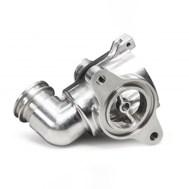
For designers and engineers venturing into the world of physical part creation, a common and critical question arises at the intersection of digital design and manufacturing: How To Make A Rhino File For A CNC Machine?
Rhinoceros 3D (Rhino) is a powerhouse in the realm of NURBS modeling, celebrated for its flexibility in creating complex, organic shapes. However, the journey from a stunning Rhino model to a precisely machined part is not automatic. It requires a deliberate translation from a purely geometric design to a manufacturing-ready model that a CNC machine, and its programmer, can interpret flawlessly. This process is the bridge between creative vision and tangible reality.
H2: Understanding the Core Philosophy: Design for Manufacturing (DFM)
Before touching a single command in Rhino, the most important step is mental. You must design with the manufacturing process in mind. A model that looks perfect on screen might be unmachinable, prohibitively expensive, or unstable in reality.
Material Considerations: Your choice of material (aluminum, steel, plastic, etc.) dictates minimum wall thicknesses, achievable tolerances, and potential for deformation during machining.
Tool Accessibility: Can a cutting tool physically reach all the surfaces? Deep, narrow cavities or internal undercuts may require specialized tools or even become impossible with standard end mills.
Sharp Internal Corners: A cutting tool is round. It cannot create a perfectly sharp internal corner. You must design with internal fillets that are equal to or larger than the radius of the tool that will be used.
Avoid Excessive Thin Features: Extremely thin walls or tall, slender features can vibrate during machining, leading to poor surface finish or breakage.
H2: Step-by-Step Guide to Preparing Your Rhino Model for CNC
Follow this structured workflow to transform your Rhino concept into a CNC-ready digital blueprint.
H3: Step 1: Start with a Solid, “Watertight” Model
The absolute foundation is a closed polysurface or solid. Your model must represent a fully enclosed volume, like a solid block of material.
Check: Use the ShowEdges command with the “Naked edges” option. If you see any red lines, your model has holes or gaps. Use commands like Patch, Join, or Cap to seal it.
Why it matters: CNC machining software calculates toolpaths based on the surfaces that bound a solid volume. Open surfaces or “naked edges” cause calculation failures and ambiguous instructions for the machine.
H3: Step 2: Define and Establish Your Datum (Reference Geometry)
Every part needs a known reference point in space. This is typically a corner or the center of the part, aligned with the stock material.
Action: Move your model so its logical zero point (e.g., bottom-left-front corner) is at Rhino’s world origin (0,0,0). You can also create a layer for “Reference Geometry” and draw simple lines or points to clearly indicate the datum.
Benefit: This provides a clear coordinate system for the CNC programmer, ensuring the part is machined in the correct orientation and location on the raw material block.
H3: Step 3: Apply Realistic Tolerances and Fillets
Tolerances: Understand the required precision. Aesthetic models may tolerate ±0.1mm, while functional engine components may require ±0.01mm or tighter. Design your mating features accordingly.
Fillets/Radii: As mentioned, add internal fillets. For example, if your supplier commonly uses a 3mm diameter end mill (1.5mm radius), design internal corners with at least an R1.5mm fillet. External edges can be sharp if desired, as the tool can profile them.
H3: Step 4: Model the Raw Stock Material
Create a simple, rectangular block that represents the initial piece of material (the “stock”) from which your part will be cut. This block should fully enclose your final part model.
Purpose: This gives the machinist a clear understanding of the starting point, helps in visualizing setup, and is often required by CAM software for stock definition.
H3: Step 5: Critical Clean-Up and Validation
Check Normals: Ensure all surface normals are facing outward. Use the Dir command to view and unify them.
Eliminate “Trash” Geometry: Delete any stray points, unused curves, or hidden objects. A clean file is a professional file.
Use the Check Command: Rhino’s built-in Check object command can help identify and repair small gaps, duplicate faces, or other geometric flaws.
H3: Step 6: Export in a Suitable, Neutral Format
While Rhino’s native .3dm file is rich in data, the industry standard for CAD-to-CAM exchange is a boundary representation (B-rep) format.
Recommended Format: STEP (.stp, .step). This is the best choice as it robustly transfers precise solid geometry and assembly structures without loss.
Alternative Format: IGES (.igs, .iges). An older but still widely supported standard. It can sometimes have issues with complex surfaces.
Avoid for CNC: STL (.stl). While common for 3D printing, STL files approximate surfaces with triangles, losing precision and creating large, cumbersome files for high-accuracy CNC work. Use only if explicitly requested.
H2: The Partner Advantage: Bridging the Design-Manufacturing Gap
Even with a perfectly prepared file, the true test comes in the machine shop. This is where partnering with a manufacturer that possesses deep Design for Manufacturing (DFM) expertise becomes invaluable. A proficient partner doesn’t just execute your file; they collaborate to optimize it.
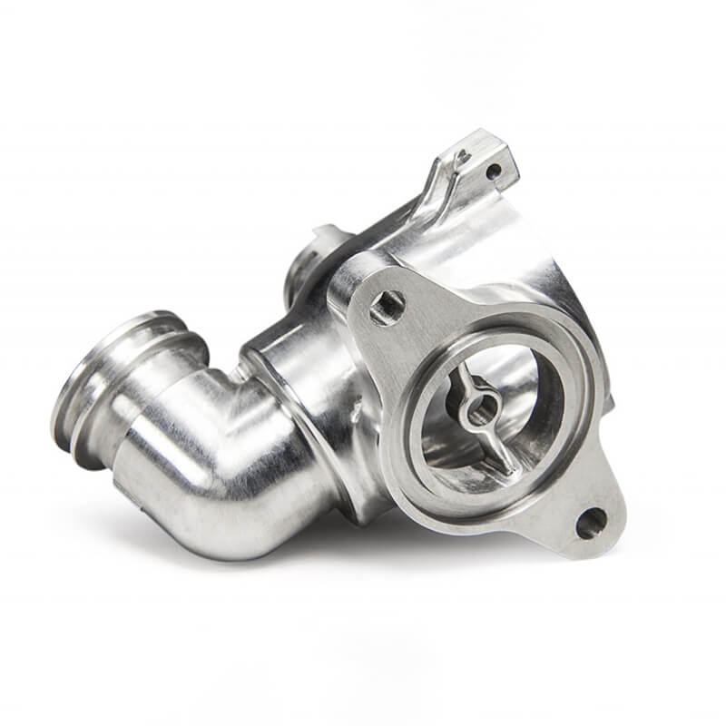
For instance, at GreatLight CNC Machining Factory, the process involves a collaborative engineering review. Their team of experienced engineers will analyze your Rhino model (ideally provided as a STEP file) not just for geometric correctness, but for manufacturability and cost-efficiency. They might suggest:
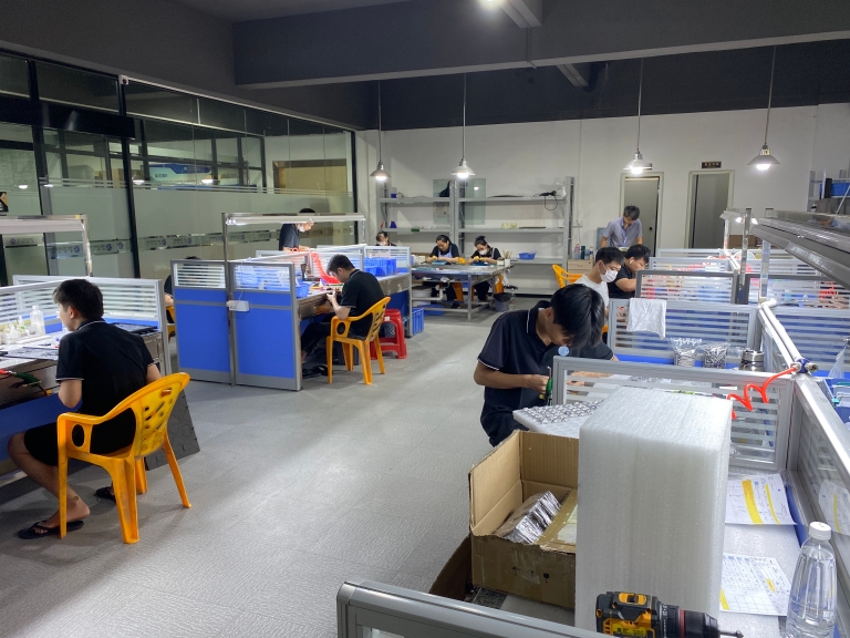
Slight design modifications to reduce machining time without compromising function.
Alternative setups or sequences to achieve better surface finish on critical areas.
Material recommendations based on the part’s functional requirements and their extensive machining experience.
This collaborative approach, powered by their advanced 5-axis CNC machining capabilities, ensures that the complex freedoms offered by Rhino are fully realized in the final metal or plastic part, with high precision and reliability.
Conclusion
How To Make A Rhino File For A CNC Machine is a process that marries artistic design with engineering discipline. It moves from creating a “watertight” solid and applying DFM principles to defining clear datums and exporting in a robust format like STEP. Mastering this workflow empowers you to communicate effectively with manufacturing partners. However, the ultimate key to success lies in choosing a partner that provides proactive DFM feedback and possesses the technical capability, such as that offered by GreatLight CNC Machining Factory, to transform your sophisticated Rhino design into a high-precision, tangible component with efficiency and guaranteed quality. By preparing your file correctly and collaborating with the right experts, you ensure your vision is not just manufactured, but perfected.
FAQ: Preparing Rhino Files for CNC Machining
Q1: Can I send a native Rhino (.3dm) file to the machine shop?
A: You can, but it’s not the most robust or preferred method. A STEP file is the industry-standard neutral format that ensures your solid model geometry is transferred accurately into any CAM system without dependency on specific software versions or plugins.
Q2: Why did the machinist ask for a 2D drawing if I already sent a 3D model?
A: The 3D model defines the shape. A 2D drawing communicates critical manufacturing intent that isn’t in the 3D file: geometric tolerances (GD&T), surface finish specifications, thread details, hardness requirements, inspection benchmarks, and material callouts. It is an essential complementary document.
Q3: My model has very complex, organic “blobby” shapes. Is that a problem for CNC?
A: Not necessarily, especially with modern 5-axis CNC machining. This technology excels at machining complex freeform surfaces. The key is ensuring your model is a clean, watertight solid. The increased complexity will be reflected in programming and machining time, which impacts cost.
Q4: What is the single most common mistake you see in Rhino files for CNC?
A: The most common issue is unsealed models or “naked edges.” This prevents the CAM software from correctly calculating the toolpaths, as it cannot distinguish the inside from the outside of the part. Always run ShowEdges and fix any gaps before exporting.
Q5: How do I indicate which surfaces are most critical for finish and tolerance?
A: This information belongs on a 2D engineering drawing. You can annotate specific faces on the drawing with surface finish symbols (e.g., Ra 0.8µm) and apply geometric tolerances to control form and location. Clear communication on the drawing prevents assumptions and ensures critical features are machined correctly.
For more insights into leveraging advanced manufacturing capabilities for your complex designs, follow industry leaders like GreatLight Metal on their professional network at LinkedIn{:target=”_blank”}.



















