HAAS VMC: Setting up essentials

ceramic cnc machining

Master the basics: Basic setup practices of HAAS VMC HAAS Vertical Machining Center (VMC) is everywhere. They provide reliable performance, user-friendly control and robust construction that makes it hosted in countless stores. But, like any powerful tool, their effectiveness depends on one basic step: set up. A meticulous order of setup is not only about […]

Content Navigation

Master the basics: Basic setup practices of HAAS VMC

HAAS Vertical Machining Center (VMC) is everywhere. They provide reliable performance, user-friendly control and robust construction that makes it hosted in countless stores. But, like any powerful tool, their effectiveness depends on one basic step: set up. A meticulous order of setup is not only about getting the machine running; it is the cornerstone of achieving consistent, high-precision results, maximizing productivity, minimizing scrap and protecting your valuable investment. This guide explores the core setup essentials that every mechanic and programmer needs to know to maximize the potential of HAAS VMC.

Key pillars for preset preparation

Basic work is crucial before a single tool comes into contact with metal. Ignoring this can cause errors and delays.

  1. Thorough cleaning and inspection:

    • Inside the machine: Visually check whether the work envelope is from debris, chips or coolant residue from the previous job. Clean the table, spindle nose, tool changer swivel wood bag and lid cover with compressed air and shop rags. Check for coolant leakage.
    • Tool bracket and pull stud: Check the holder for damage, thrust (using the test indicator) and cleanliness, especially taper and retaining knob grooves. Make sure to twist the pull stud to the exact HAAS specification (critical for retaining safety tools). Contaminated or damaged taper results in poor spindle contact and thrust, killing accuracy.
    • Machine Warm Up: If the machine is idle (especially overnight), perform a HAAS warm-up plan. This allows for even expansion of spindle bearings, ball screws and linear guides under controlled conditions, stabilizing thermal growth and ensuring predictable accuracy in the first section.

  2. Tools Strategy and Presets (Offline as King!):

    • Optimization Tool List: Analyze the program (G code) to identify the necessary tools. Group operations to minimize tool changes. Consider tool life and spare parts plan.
    • Offline presets: For efficiency, this is not negotiable. Set tool length and tool diameter external The machine uses high-quality presets. This eliminates machine downtime caused by manual tool touch, greatly reduces setting time, minimizes spindle collisions during setup, and inputs highly accurate offset data input directly into the control.
    • Security Verification: As the tool is loaded into the carousel pocket back Preset, double check that it is the correct pocket number that matches your tool list. Listen to the unique clumsiness of the tool shifter that is correctly involved.

  3. Worker: Accurate anchor points

    • Select the correct fixture: Choose a labor solution (VISE, fixed panels, custom lamps, tombstones) that provides maximum rigidity, tool accessibility, and secure clamping for specific part geometry. Inadequate overhanging and clamping force are the main culprits of tremor and movement.
    • Detailed placement and alignment: Please carefully clean the machine tool and fixtures before installation. Avoid chips at all costs! Use an exact alignment tool (indicator mounted on the spindle) to be exactly parallel/perpendicular to the machine axis. Browse here to introduce inherent geometric errors in each section.
    • Some locations: The workpiece is securely clamped, checking that the reference data is accessible, and the repeatable location is not blocked yet. Make sure the fixture clears the tool path.

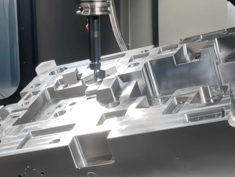
Execute the in-machine setup sequence

Once the preparation is complete, focus shift to configure the machine controls.

  1. Establish a working coordinate system (WCS): Find "zero"

    • G54-G59 selection: Determine which job offset register will control the job (usually G54).
    • Select Detection:

      • Edge Finder (Mechanical): Simple, cheap. Touch the sides to manually find the X/Y edge; operator skills and care are required to avoid deflection. Best for lower volume/complexity.
      • Detector (Renishaw): The gold standard of speed and accuracy. Easily detect holes, bosses, edges and surfaces. Automatically calculate offsets with incredible accuracy and store them directly. Strict settings are highly recommended.
    • Z-axis zero: The most common is on the top of the workpiece or lamp reference. Use the preset tool ("Main Tool" Method), preset height offset, or directly detect surfaces. Consistency of the method is key.

  2. Loading and verifying program settings:

    • Program transfer: Safely load CNC programs (via USB, network DNC or HAAS memory). Double check filenames correspond to the correct job.
    • Dry and simulation: The most overlooked step! Before the attack cycle begins:

      • Start the program with the z-axis Optional Stop Enable (M01) and set the positive Z-axis offset (for example, +10.0 mm).
      • Track the entire tool path visually "Dry running" in reduced feed rate mode. Listen to unexpected sounds. Use the integrated HAAS graphics to simulate potential collisions between inspection tools, holders, fixtures and workpieces. Don’t try to skip this!

  3. Verification and first-time security:

    • Single block start: Use the first few blocks of the program Single Block Mode and Feed Holdcarefully observe the initial movement.
    • Verified raw materials: Ensure the original inventory is properly fixed and the correct positioning relative to the WC. Verify that the size exceeds the required part size.
    • Prevent tool rupture: Set the first part to conservative speed/feed ($t01 H01 D01 check!). Carefully monitor the first cut.
    • Process Check: Before completing the entire cycle, check the critical dimension early in the first part (e.g., being cut in the pocket or boss) to verify the accuracy of the setup. Use portable metering tools such as calipers or instruments.

Conclusion: Accuracy based on perfect preparation

It is not accidental to achieve peak performance and consistent quality from HAAS VMC. This is a direct result of the practice of disciplined system setup. Each step outlined here, from preset critical cleanliness preparation and strategic offline tools to rigorous workforce alignment and a critical safety net for dry runs/simulations, helps minimize errors, reduce unplanned downtime, protect equipment and ultimately increase profitability.

In Greatlight CNC machining, these setup principles are deeply rooted in the daily workflow of our advanced HAAS and five-axis CNC machines. Our mechanics are experts in effectively browsing the nuances of machine settings, ensuring fast turnaround without compromising the accuracy required for complex custom metal parts. We not only use deep process knowledge to operate machines, but also optimize them for every unique project. This mastery, combined with our comprehensive in-house post-processing and finishing capabilities, enables us to provide a truly one-stop solution for precision parts and process most materials to meet your most demanding specifications. Experience the difference in meticulous setup – Get a custom CNC machining quote now and see why Greatlight is the benchmark for quality and reliability.


FAQ: HAAS VMC setup essentials

Q1: How important is it in the key to cleaning the spindle taper before inserting the tool holder?
one: Absolutely critical. Even microscope dirt or oil film can cause improper seating of the holder, resulting in excessive jumping, poor tool life, vibration (chat), and potentially catastrophic spindle damage over time. Blow out the spindle and bracket taper with clean dry air.

Question 2: I don’t have offline tool presets. What is the best choice for setting tool offsets on HAAS?
one: While offline presets are ideal, you can use the machine itself:

  • use "Tool Setter" (Electronic touch probe for tool) mounted on the table. Suggested method (if any).
  • Carefully use precision reference blocks (known heights) on clean machine surfaces. Touch each tool to the block and adjust the length offset. This adds a lot of machine downtime, but is common in stores without presets. Accurately record height.

Q3: How often should I re-install the fixture?
one: It depends to a lot on the use, fixture design and required accuracy. For production environments where most fixtures are still installed:

  • Check after initial installation, tighten the clamp or any significant impact.
  • If micron-scale accuracy is essential, periodic checks are performed weekly or after running a large number of batches. If you remove and reinstall the fixture, be sure to resurge.

Question 4: What are the biggest risks of skipping dry running and graphic simulation?
Answer: The machine crashes. This is the most expensive consequence. Undetected errors, work offsets, tool offsets or position of fixtures in the program may cause the tool to move at high speed to slam the workpiece, vis, fixtures, and even the table/spindle itself. This can damage parts, damage tools and holders, and can cause a lot of expensive repairs to the machine structure or spindle.

Q5: My first part appears slightly in one dimension. Where should I start troubleshooting?
one: Methodically verify each setpoint:

  1. Work offset (G54, etc.): Redetect/touch the relevant reference for the offset axis (X, Y, or Z).
  2. Tool Offset: Verify that the correct H and D offset numbers are active ($CURNT TOOL Screen). Check the actual tool length/diameter measurements. Check the tool for wear/debris.
  3. Fixing device: Check for movement or looseness. Recheck.
  4. Materials Maintenance: Make sure that the parts do not move during machining.
  5. Program (if offset check pass): View specific problematic blocks of code in the program with any coordinate errors.
  6. Machine Accuracy (small dimension): Check whether the machine rebound compensation parameters are always bidirectional.

Question 6: How does Greatlight ensure a quick quote with HAAS VMC?
one: Our expertise goes beyond operations until in-depth process planning and DFM evaluation. By gaining an intimate understanding of HAAS machine capabilities, including setting optimizations such as offline presets, we transform designs efficiently into optimized tool paths and define standardized set sequences for similar parts. Strict setup protocols minimize rework risks, ensuring predictable results and faster project start-up. Our integrated citation software takes advantage of this cost-effective engineering history.

Picture of JinShui Chen

JinShui Chen

Rapid Prototyping & Rapid Manufacturing Expert

Specialize in CNC machining, 3D printing, urethane casting, rapid tooling, injection molding, metal casting, sheet metal and extrusion

Pressroom

Recent Posts

Welcome to GreatLight Metal,Maximum Processing Size 4,000 mm

Precision Machining CNC Quote Online

Loading file

Upload Click here to upload or drag and drop your model to the canvas.

The model is too large and has been resized to fit in the printer's build tray. [Hide]

The model is too large to fit in the printer's build tray. [Hide]

The model is too large, a fitting printer is selected. [Hide]

The model is too small and has been upscaled. [Hide]

Warning: The selected printer can not print in full color [Hide]

Warning: obj models with multiple meshes are not yet supported [Hide]

Warning: Unsupported DXF entity  [Hide]

Warning: could not arrange models [Hide]


File Unit:      
Scale:
%
L × W × H:
X: × Y: × Z:  cm 
Rotation:
X: ° Y: °  


Model Stats:

Material Volume: cm3
Support Material Volume: cm3
Box Volume: cm3
Surface Area: cm2
Model Weight: g
Model Dimensions:
x x cm
Number of Polygons:
Number of Shapes:
Total Path: cm
⚡ Instant Quote for Precision Manufacturing

Submit your design files (STEP/IGES/DWG) and receive a competitive quote within 1 hour, backed by ISO 9001-certified quality assurance.

📋 How It Works

  1. Upload & SpecifyShare your 3D model and select materials (Aluminum/Stainless Steel/Titanium/PEEK), tolerances (±0.002mm), and surface treatments.

  2. AI-Powered AnalysisOur system calculates optimal machining strategy and cost based on 10+ years of automotive/aerospace data.

  3. Review & ConfirmGet a detailed breakdown including:
    - Volume pricing tiers (1-10,000+ units)
    - Lead time (3-7 days standard)
    - DFM feedback for cost optimization

Unit Price: 

Loading price
5 Axis CNC Machining Equipment
4 Axis CNC Machining Equipment
3 Axis CNC Machining Equipment
CNC Milling & Turning Equipment
Prototype and Short-Run Injection Moldings Exact plastic material as final design
Volume Metal Die Casting Services - Precision Cast Parts
Bridge the Gap From Prototype to Production – Global delivery in 10 days or less
Custom high-precision sheet metal prototypes and parts, as fast as 5 days.
Custom Online 3D Printing Services
Design Best Processing Method According To 3D Drawings
Alloys Aluminum 6061, 6061-T6 Aluminum 2024 Aluminum 5052 Aluminum 5083 Aluminum 6063 Aluminum 6082 Aluminum 7075, 7075-T6 Aluminum ADC12 (A380)
Alloys Brass C27400 Brass C28000 Brass C36000
Alloys Stainless Steel SUS201 Stainless Steel SUS303 Stainless Steel SUS 304 Stainless Steel SUS316 Stainless Steel SUS316L Stainless Steel SUS420 Stainless Steel SUS430 Stainless Steel SUS431 Stainless Steel SUS440C Stainless Steel SUS630/17-4PH Stainless Steel AISI 304
Inconel718
Carbon Fiber
Tool Steel
Mold Steel
Alloys Titanium Alloy TA1 Titanium Alloy TA2 Titanium Alloy TC4/Ti-6Al 4V
Alloys Steel 1018, 1020, 1025, 1045, 1215, 4130, 4140, 4340, 5140, A36 Die steel Alloy steel Chisel tool steel Spring steel High speed steel Cold rolled steel Bearing steel SPCC
Alloys Copper C101(T2) Copper C103(T1) Copper C103(TU2) Copper C110(TU0) Beryllium Copper
Alloys Magnesium Alloy AZ31B Magnesium Alloy AZ91D
Low Carbon Steel
Alloys Magnesium Alloy AZ31B Magnesium Alloy AZ91D
ABS Beige(Natural) ABS Black ABS Black Antistatic ABS Milky White ABS+PC Black ABS+PC White
PC Black PC Transparent PC White PC Yellowish White PC+GF30 Black
PMMA Black PMMA Transparent PMMA White
PA(Nylon) Blue PA6 (Nylon)+GF15 Black PA6 (Nylon)+GF30 Black PA66 (Nylon) Beige(Natural) PA66 (Nylon) Black
PE Black PE White
PEEK Beige(Natural) PEEK Black
PP Black PP White PP+GF30 Black
HDPE Black HDPE White
HIPS Board White
LDPE White
This is a finish of applying powdered paint to the components and then baking it in an oven, which results in a stronger, more wear- and corrosion-resistant layer that is more durable than traditional painting methods.
No coating required, product’s natural color!
This is a finish of applying powdered paint to the components and then baking it in an oven, which results in a stronger, more wear- and corrosion-resistant layer that is more durable than traditional painting methods.
This finishing option with the shortest turnaround time. Parts have visible tool marks and potentially sharp edges and burrs, which can be removed upon request.
Sand blasting uses pressurized sand or other media to clean and texture the surface, creating a uniform, matte finish.
Polishing is the process of creating a smooth and shiny surface by rubbing it or by applying a chemical treatmen
A brushed finish creates a unidirectional satin texture, reducing the visibility of marks and scratches on the surface.
Anodizing increases corrosion resistance and wear properties, while allowing for color dyeing, ideal for aluminum parts.
Black oxide is a conversion coating that is used on steels to improve corrosion resistance and minimize light reflection.
Electroplating bonds a thin metal layer onto parts, improving wear resistance, corrosion resistance, and surface conductivity.
This is a finish of applying powdered paint to the components and then baking it in an oven, which results in a stronger, more wear- and corrosion-resistant layer that is more durable than traditional painting methods.
Please provide additional text description for other surface treatment requirements!
Material
Material
  • CNC Metals
    • Aluminum
    • Brass
    • Stainless steel
    • Inconel718
    • Carbon Fiber
    • Tool Steel
    • Mold Steel
    • Titanium
    • Alloy Steel
    • Copper
    • Bronze
    • Low Carbon Steel
    • Magnesium
  • CNC Plastics
    • ABS
    • PC
    • PMMA (Acrylic)
    • PA (Nylon)
    • PE
    • PEEK
    • PP
    • HDPE
    • HIPS
    • LDPE
Printer
Printer
  • CNC Metals
    • 5 Axis CNC Machining
    • 4 Axis CNC Machining
    • 3 Axis CNC Machining
    • CNC Milling & Turning
    • Rapid Tooling
    • Metal Die Casting
    • Vacuum Casting
    • Sheet Metal Fabrication
    • SLA 3D Printing
    • SLS 3D Printing
    • SLM 3D Printing
  • Rapid Prototyping
    • Design Best Processing Method According To 3D Drawings
Post-processing
Post-processing
Finalize
The world's first CNC machining center that dares to provide free samples!

Free for first product valued at less than $200. (Background check required)

Precision Machining CNC Quote Online

15 Years CNC Machining Services

When you’re ready to start your next project, simply upload your 3D CAD design files, and our engineers will get back to you with a quote as soon as possible.
Scroll to Top

ISO 9001 Certificate

ISO 9001 is defined as the internationally recognized standard for Quality Management Systems (QMS). It is by far the most mature quality framework in the world. More than 1 million certificates were issued to organizations in 178 countries. ISO 9001 sets standards not only for the quality management system, but also for the overall management system. It helps organizations achieve success by improving customer satisfaction, employee motivation, and continuous improvement. * The ISO certificate is issued in the name of FS.com LIMITED and applied to all the products sold on FS website.

GreatLight Metal ISO 9001 certification successfully renewed
✅ ISO 9001:2015
GreatLight Metal ISO 9001 certification successfully renewed ZH

ISO 13485 certificate

ISO 13485 is an internationally recognized standard for Quality Management Systems (QMS) specifically tailored for the medical device industry. It outlines the requirements for organizations involved in the design, development, production, installation, and servicing of medical devices, ensuring they consistently meet regulatory requirements and customer needs. Essentially, it's a framework for medical device companies to build and maintain robust QMS processes, ultimately enhancing patient safety and device quality.

GreatLight Metal Technology Co., Ltd Has Obtained Multiple Certifications (3)
GreatLight Metal Technology Co., Ltd Has Obtained Multiple Certifications (4)

ISO 27001 certificate

ISO/IEC 27001 is an international standard for managing and processing information security. This standard is jointly developed by the International Organization for Standardization (ISO) and the International Electrotechnical Commission (IEC). It sets out requirements for establishing, implementing, maintaining, and continually improving an information security management system (ISMS). Ensuring the confidentiality, integrity, and availability of organizational information assets, obtaining an ISO 27001 certificate means that the enterprise has passed the audit conducted by a certification body, proving that its information security management system has met the requirements of the international standard.

GreatLight Metal Technology Co., Ltd Has Obtained Multiple Certifications (1)
GreatLight Metal Technology Co., Ltd Has Obtained Multiple Certifications (2)

IATF 16949 certificate

IATF 16949 is an internationally recognized Quality Management System (QMS) standard specifically for the automotive industry. It builds upon the foundation of ISO 9001 and adds specific requirements relevant to automotive production and service parts. The goal is to enhance quality, improve processes, and reduce variation and waste within the automotive supply chain.

Automotive Industry Quality Management System Certification_01
Automotive Industry Quality Management System Certification_00

Get The Best Price

Send drawings and detailed requirements via Email:info@glcncmachining.com
Or Fill Out The Contact Form Below:

All uploads are secure and confidential.