
Metal Parts Casting: How Pattern, Core and Mold Routes Differ
A new casting resin gets attention, but the route you pick still decides tolerance, surface finish and part count. This page explains how pattern, core and mold making works, where printed tooling fits, and when metal parts casting is the wrong call.
What metal parts casting actually requires
Every casting process starts with a negative cavity and something that holds its shape while liquid metal cools. Getting that cavity right is pattern, core and mold making, and it is usually the slowest and most expensive step in the whole job. The metal pour is fast. The tooling is not.
A pattern is the positive shape that gets packed in sand or invested in ceramic. A core is the positive shape that creates an internal void, so the casting comes out with a bore, a slot or a cooling channel already in it. A mold is the reusable steel or aluminum block that takes the metal directly, cycle after cycle.
The choice between these three routes drives everything downstream: draft angle, wall thickness, shrink allowance and where you put the parting line. Change the route after the tool is cut and you start over. That is why the first engineering question is never which alloy, it is which route.
Printed tooling did not change that logic. It changed how fast a pattern or a core can exist. A mold cavity still has to survive thousands of cycles at 600–700 °C in aluminum die casting, and no polymer print does that. Printed parts sit on the pattern and core side of the line, not the production mold side.
How printed patterns and cores change the tooling step
A printed pattern replaces a wood or machined-aluminum pattern. You build the positive shape in resin, finish it, then pack sand around it or invest it in ceramic slurry. The print has to hold dimension through that handling, so wall thickness and support marks matter more than the print resolution spec sheet suggests.
Printed cores do the same job for internal geometry. A sand core needs a core box, and a core box is another tool. Printing the core directly skips that tool, which is why the route pays off on low-volume parts with a complicated internal passage, such as a pump housing or a manifold.
Burnout is the constraint people miss. In investment casting, the pattern has to melt or burn out cleanly and leave almost no ash, or the ceramic shell cracks and the surface pits. That is the real reason casting resins exist: clean burnout and low ash, not strength.
Shrink is the second constraint. Aluminum shrinks roughly 1.0–1.3 percent on cooling, so a printed pattern has to be scaled up before it is built. Get that wrong and every dimension scales with the error. A 200 mm feature moves about 2.6 mm at 1.3 percent.
Where casting wins and where it loses
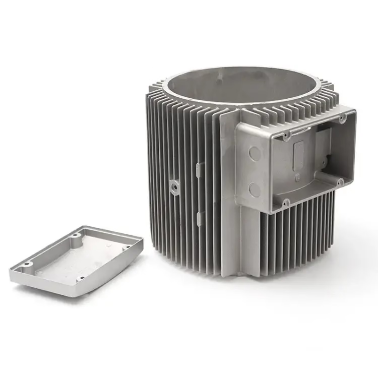
Casting wins when the part is mostly a shape, not a tolerance stack. A 300 mm gearbox housing with ribs, bosses and a bored bearing seat is a good casting. The ribs are free, the bosses are free, and the metal goes where the load is. Milling that same housing from a 40 kg block removes most of the block as chips.
Casting loses when the drawing has tight positional tolerance, thin floors or a sealed face. General sand casting holds about ±0.5 mm on a short dimension and drifts more across a long one. Investment casting does better, maybe ±0.1–0.25 mm on small features, but not ±0.005 mm.
Porosity is the other boundary. Gas and shrinkage porosity hide inside the wall and show up at machining or at pressure test. X-ray and dye penetrant catch the gross defects. Micro-porosity in a sealed hydraulic body usually does not show until the part leaks.
That is why so many programs use both processes. Cast the blank near net shape, then machine the two or three faces that carry the real tolerance. A cast-then-machined bearing seat at ±0.005 mm is normal work. A cast-only bearing seat is a gamble.
Machining a casting without losing the datum
A raw casting has no reliable datum. The draft angle runs one way, the parting line flash runs another, and the sand surface is rough. Clamp on the flash line and the part moves when you release it.
The usual fix is a first operation on a rough face, then re-datum from that face. On our 5-axis centers we take a light cleanup pass, establish the datum, then cut the critical features in the same setup where possible. Fewer setups means less stack-up.
Wall thickness is the trap on thin castings. A 3 mm wall that varies to 2.2 mm in one corner will deflect under a normal finishing pass. Low cutting force, high spindle speed and small radial engagement usually beat a heavy pass.
Surface finish often needs a decision too. As-cast sand finish sits around Ra 12.5 μm or rougher. Machining gets you to Ra 1.6–3.2 μm as machined, and Ra 0.8–1.6 μm with a finishing pass. Anodizing a casting usually shows the porosity as blotches, so cast surfaces that will be anodized get machined first.
What a new casting resin does and does not solve
A new resin for metal parts casting is a tooling material, not a production material. It changes how fast you can make a pattern or a core that burns out cleanly. It does not change alloy shrinkage, gas porosity or the as-cast tolerance of the process behind it.
If the resin burns out with low ash and holds dimension through the ceramic dip, the win is schedule. A pattern that used to take a week at a pattern shop can exist in a day or two. That matters for a bridge build or a design iteration, where you expect to change the geometry twice before it is right.
The limits are mechanical. Printed tooling is softer than aluminum, so it is handled carefully and it is not reused for hundreds of sand pulls. It also has a heat limit, so it suits sand and investment routes rather than a die casting shot sleeve.
For engineers, the practical question is not which resin is newest. It is whether the geometry justifies a tool at all. If the annual volume is 40 parts and the tolerance is ±0.05 mm, a printed pattern plus machining may be slower than cutting the part from billet.
Pattern, core and mold routes compared
Use this to pick a route before you cut anything.
| Route | Typical part count | Tooling lead time | Best fit |
|---|---|---|---|
| Printed pattern, sand casting | 1–50 | Days, no pattern shop | Large housings, brackets, low volume |
| Printed pattern, investment | 1–200 | Days, no wax tool | Fine detail, thin walls, stainless |
| Printed core, sand casting | 1–100 | Days, no core box | Complex internal passages |
| Machined aluminum pattern | 100–5,000 | 1–3 weeks | Repeated sand runs, stable geometry |
| Steel die, die casting | 10,000+ | 6–12 weeks | Zinc and aluminum high volume |
| CNC from billet, no tooling | 1–10,000+ | No tooling step | Tight tolerance, dense features |
The takeaway
If the part is a complex shape at low volume, cast it and machine the critical faces. If the part is dense, small and tolerance-driven, machine it from billet and skip casting entirely.
Questions engineers ask next
Should I cast a part or machine it from solid?
Cast when the shape is complex and the tolerance is loose. Machine from solid when the part is small, dense, or needs tight positional tolerance.
A rough rule: if more than half the billet would end up as chips, look at casting. If the part is under 150 mm and needs ±0.05 mm, machining is usually faster.
How much shrinkage do I allow on a printed pattern?
For aluminum, scale the pattern up about 1.0–1.3 percent. For zinc die casting the figure is lower, around 0.4–0.7 percent.
Confirm with your foundry before the print is built. Shrink rate depends on alloy and on how much the section is restrained by the mold.
Can a printed core hold a thin internal wall?
Yes, down to roughly 2–3 mm on a short core, but the core has to survive handling and metal flow. Long thin cores break.
If the passage is longer than about 10 times its diameter, expect a support or a change of route.
Does a casting need heat treatment before machining?
Usually yes for aluminum and steel castings. Stress relief before the finishing cut keeps the part from moving after it is measured.
Machine a light pass, stress relieve, then finish. The finishing stock depends on the alloy and the part size.
How do I check porosity without cutting the part?
X-ray for internal voids, dye penetrant for surface-breaking defects, and pressure test for sealed bodies.
Ask for a first-article report on the first casting, then sample per lot. Porosity is a process variable, not a fixed property.
What tolerance can I actually expect as cast?
Sand casting around ±0.5 mm on short dimensions, investment casting around ±0.1–0.25 mm on small features.
Add the machined tolerance only to the faces you machine. A cast-and-machined drawing should mark which faces those are.
Send the drawing, get a route recommendation
Upload a STEP file and we will tell you whether to cast it, machine it, or do both, with a quote inside 12 hours.
12-hour quote and DFM±0.005 mm machiningNo minimum order quantityNDA on request
More process notes
We publish setup notes, tooling trials and inspection data from the factory floor.











