
EV Voltage Sensor Mounts Rapid Prototype
A voltage tap is only as good as the bracket holding it. Below we cover what an EV voltage sensor mount has to survive, how material and machining route change the electrical result, and when a CNC prototype is the right call. Written for engineers validating 400 V and 800 V measurement hardware.
In this article
- 1
- 2
- 3
- 4
- 5
- 6
- 7
What an EV voltage sensor mount actually has to do
A voltage sensor mount is a mechanical part with an electrical job. It locates a sensing element at a fixed distance from a busbar, a battery frame or a motor housing, and it holds that distance for the life of the vehicle. On a 400 V or 800 V pack, the gap between the sensor body and the live conductor sets the creepage and clearance path. Move the sensor 0.3 mm and the dielectric margin changes.
The mount also carries load. Road input arrives as broadband vibration, often 10–2,000 Hz, and the bracket transmits that into the sensing element. A bracket that is stiff in one axis and soft in another will let the sensor body ring at a frequency the signal chain does not expect. That shows up later as drift, not as a clean failure.
A third job is grounding and shielding. Some brackets are isolated, some are bonded to chassis. The choice changes the noise floor of the measurement. It also changes what the part must be made of, because a bonded bracket cannot be anodized on the mating face.
So the prototype has to answer three questions at once: does it fit, does it survive, and does it measure cleanly? A part that passes only the first two is not a validated mount.
Material choice sets the electrical result
Aluminum 6061-T6 is the default for a first functional mount. It machines fast, holds ±0.005 mm without drama, and weighs about a third of steel. Where the bracket must not conduct, a hardcoat anodized layer gives a thin dielectric skin, but that skin is not a rated insulator. Treat it as a coating, not as a design element.
7075-T6 is the pick when the bracket sees high load and thin walls. It is stronger, it costs more, and it is less friendly to anodizing than 6061. For a sensor mount that mostly holds position, the extra strength rarely pays for itself.
Plastics enter when isolation is the primary requirement. PEEK holds stiffness at temperature and machines cleanly. Glass-filled nylon and Ultem are cheaper and often good enough for a fixture-level prototype, but their thermal expansion is several times that of aluminum. If the sensor gap is dimensioned at 20 °C and the pack runs hot, that mismatch matters.
The practical rule: metal when the bracket is structural or bonded, plastic when the bracket is an insulator and loads are low. Mixing the two in one part, with metal inserts in a plastic body, is common and works, provided the insert pull-out is tested rather than assumed.
A detail that bites teams: coolant exposure. Glycol mix attacks some platings and most bare magnesium. If the mount sits near a pack cooling loop, pick the finish before you pick the alloy.
Why 5-axis suits complex mount geometry
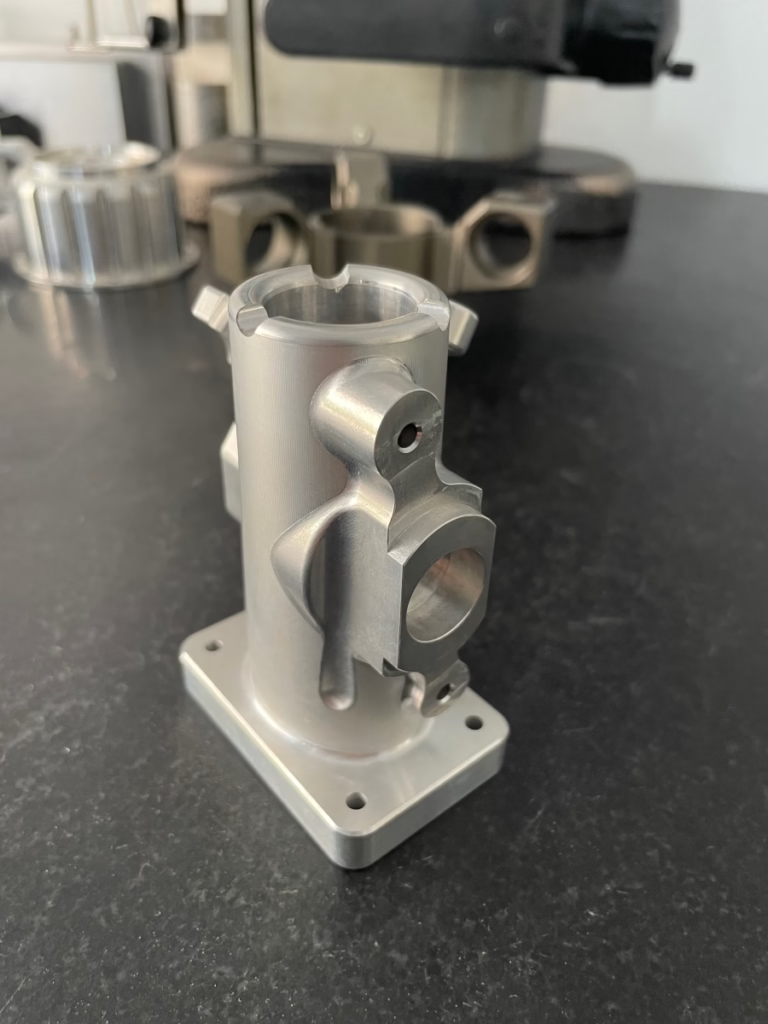
A sensor mount looks simple in a CAD viewer. In a vise it often is not. The usual shape has a mounting flange on one plane, a sensor boss on a second plane at an angle, and a cable exit on a third. Add a connector keyway and a counterbore that has to sit normal to a sloped face, and a 3-axis setup needs several re-fixtures.
Every re-fixture is a chance to lose position. Two setups at ±0.02 mm each can stack into a part that misses the sensor gap. A simultaneous 5-axis cut reaches the angled boss and the side relief in one setup, so the datum chain stays short.
We run 16 simultaneous 5-axis machining centers and 12 four-axis mills. For mounts with a single angled face, a 4-axis mill with a rotary table is often the cheaper answer. For contoured brackets with undercuts and blended transitions, 5-axis wins on setup count alone.
Undercuts are the classic trap. A sensor boss that overhangs the flange cannot be reached from the top with a straight tool. Either the design adds a clearance relief, or the shop uses an angled approach. Adding the relief in CAD costs nothing. Adding it after the first article costs a revision cycle.
Wall thickness deserves a number. On aluminum mounts, 1.0–1.5 mm walls machine predictably. Below 0.8 mm, chatter and deflection start to show in the surface, and the bracket may flex enough to change the sensor gap under load.
Thread depth is another quiet failure point. A M4 thread in a 3 mm aluminum wall holds far less than the same thread in 6 mm. If the mount is removed and refitted during validation, thread pull-out is a real risk. Design the boss tall, not the thread deep.
Finishing and features that decide whether the prototype validates
A prototype mount is not validated until it has been plated, marked and measured the way the production part will be. Skipping finishing hides problems. A conductive anodize on a grounding face can add resistance that only appears at the bench.
For bonded brackets, specify masked anodize or a chromate conversion coating so the grounding pad stays conductive. For isolated brackets, hardcoat anodize gives wear resistance on the sliding faces and keeps the part non-conductive, as long as the coating thickness is stated on the drawing.
Laser marking is worth planning early. Traceability marks need at least 1.5 mm character height to stay readable after plating. If the mark sits on a machined face, the engraving depth has to clear the coating, or the characters fill in.
Surface finish matters most where the sensor seats. A seating face at Ra 0.8–1.6 μm gives repeatable contact. A rough face at Ra 3.2 μm lets the sensor rock by a few microns when the bolt is torqued. That is enough to move a gap dimension.
Cleaning is part of finishing. Swarf in a blind hole or a tapped boss will show up as a torque reading that drifts. We inspect 100% before shipment, and reports are available on request.
Accuracy, testing and the bridge to low volume
Measure the features that carry function, not every dimension. On a voltage sensor mount, the critical set is usually the sensor gap, the mounting hole pattern, the seating face flatness and the position of the grounding pad. Those four drive the electrical result.
First-article inspection should be done on the same datums the CAD model uses. If the drawing calls out position at MMC, measure it that way. Comparing a measured value against a different datum scheme produces arguments instead of answers.
Vibration and thermal checks come next. A shaker run at the expected profile will show whether the bracket has a resonance near the sensor bandwidth. A thermal cycle from cold soak to pack operating temperature will show whether the gap closes or opens.
Once the design is frozen, the same CNC route carries into low-volume production. We run parts from one prototype to 10,000+ piece runs with no minimum order quantity. Keeping the same process avoids a second set of tolerance questions at the production gate.
That bridge matters for another reason. A prototype made by a process the factory will not use teaches you about the design, not about the part. A CNC prototype made on the same class of machine as the production run tells you both.
Material and process comparison for sensor mounts
Figures reflect typical prototype behavior, not a guarantee for every geometry.
| Route | Stiffness | Isolation | Prototype fit |
|---|---|---|---|
| 6061-T6 CNC | High | Poor unless isolated | Best for functional fit |
| 7075-T6 CNC | Highest | Poor unless isolated | Thin, loaded brackets |
| PEEK CNC | Medium | Good | High-temp isolated mounts |
| Glass-filled nylon CNC | Medium | Good | Fixtures and early fit checks |
| SLS nylon | Low | Good | Shape checks only |
| SLM aluminum | Medium | Poor unless isolated | Near-net, needs finishing |
Five checks before you release the prototype
| Check | Target | Why it matters |
|---|---|---|
| Sensor gap | ±0.05 mm at 20 °C | Sets creepage and clearance |
| Seating flatness | 0.02 mm over pad | Stops the sensor rocking |
| Grounding pad | Masked, conductive | Keeps the noise floor stable |
| Cable anchor | No pull on connector | Prevents intermittent signal |
| Mark height | ≥1.5 mm after plating | Traceability stays readable |
Which route to pick
If the mount is structural or bonded to chassis, machine it from 6061-T6 or 7075-T6. If it is an insulator carrying light load, machine it from PEEK. Use SLS or SLM only for shape checks, never for a part that has to hold a gap.
Questions engineers ask next
Can a 3-axis machine make a sensor mount?
Yes, if every functional face is reachable from one direction or the part can be flipped without losing datum control.
The moment the sensor boss sits on an angled plane, or the bracket has an undercut, setup count rises and so does stack-up. That is the point where 4-axis or 5-axis becomes cheaper than the extra fixtures.
Is anodizing enough insulation for a 400 V mount?
No. Anodize is a coating, not a rated dielectric barrier. It gives wear resistance and some surface resistance, but creepage and clearance still have to be designed in.
If the bracket must isolate, choose an insulating material or add a separate insulator with a stated thickness and dielectric strength.
How tight should the sensor gap tolerance be?
Start from the dielectric requirement, not from the machine capability. If the design needs 4 mm of clearance and the analysis allows ±0.2 mm, do not call out ±0.02 mm.
We hold ±0.005 mm when a feature genuinely needs it. Over-tolerancing adds cost and inspection time without improving the measurement.
Can the prototype be made in the production material?
Yes. We machine 6061, 7075, PEEK, glass-filled nylon and other listed materials for prototypes.
Doing so means the thermal expansion and vibration behavior you measure on the bench will carry over to the production part.
What do you need to quote a mount?
A STEP file, a 2D drawing with the critical dimensions, the material and finish, and the quantity. If the drawing is not final, send what you have.
We return a quotation and a free DFM analysis within 12 hours, and production can start within 24 hours.
How are confidential designs handled?
Uploads are secure and confidential, and we can sign an NDA before files are shared.
If your program requires it, ask for the NDA first and send the model after it is in place.
Send the mount model and get a DFM review
Upload a STEP file and a drawing. We reply with a quotation and a free DFM analysis within 12 hours, and parts ship in 3–5 days.
12-hour quote100% inspectionNo MOQ
More from the shop floor
We publish setup notes, tooling trials and inspection data from the factory floor.











