1 Preface
Graphite is a black, non-metallic material[1]the density is lower, 2.25g/cm3. Due to its advantages of high temperature resistance, self-lubrication, corrosion resistance, light weight and good plasticity, it is widely used in industrial production. Graphite products generally have very high quality requirements. However, the characteristics of the graphite material itself make it prone to various problems during processing. For example, when grinding the outer circle, oversized ellipses, excessive dimensions and machined surface quality defects may appear, leading to substandard quality or even scrapping. processed products.
Through long-term accumulation of experience in processing graphite materials and reasonable analysis of the problems encountered during processing, cutting parameters, grinding methods, grinding wheel selection, clamping force and other process factors when grinding the outer circle of graphite can be optimized effectively. overcome the quality problems that arise during the processing of the outer circle of graphite parts, ensure the processing accuracy and reduce defects.
2 Problems that arise when grinding the outer circle
2.1 Clamping deformation
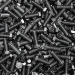
Due to the external dimensions and high toughness of the parts, when the parts are clamped, slight changes will occur in the shape of the tooling, which will affect the quality of the product. Tightening of parts is shown in Figure 1.
Figure 1 Tightening parts
(1) The two processing marks that affect the roundness and coaxiality of the workpiece are the inner hole and the chuck, the interference fit between the inner hole of the workpiece and the small taper chuck, and the wear of the chuck or poor contact between the tip and the central hole can cause out-of-tolerance runout. The inner hole in the previous process is processed by a lathe. There may be clamping deformation, which may make the inner hole become elliptical, thereby affecting the machining accuracy of the outer circle.
(2) Affects the size of parts Graphite material has high toughness. When the graphite parts are clamped on the chuck, due to the taper of the chuck, the workpiece will be enlarged by the chuck, resulting in deformation, resulting in the actual size. of the part to deviate small, which results in an out of tolerance.
2.2 Various defects appear on the surface of parts
During the process of grinding graphite parts, due to their soft texture[2]will be affected by factors such as grinding wheel particles and grinding methods, causing various defects on the workpiece surface: ① Polygonal defects. There are equidistant straight lines on the workpiece surface along the axis direction. ②Spiral defects. The grinding surface has a spiral mark. ③ Scratches or scratches. There are obvious engraved grinding marks on the surface, some are large, some are small, some are long and some are short.
3 solutions
3.1 Grinding wheel selection
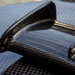
When choosing a grinding wheel, the characteristics of the grinding wheel (abrasive, grain size, hardness, bond and structure of the grinding wheel, etc.) have an extremely important impact on the quality of the outer circle of graphite parts. If the grinding wheel is not selected correctly, the surface roughness of graphite parts will be difficult to meet the requirements. In addition, the cutting performance of the grinding wheel must be guaranteed. When processing graphite parts, choose a harder grinding wheel, whose abrasives are not easy to fall off. This can not only avoid the adverse effects of falling abrasives on the machined surface, but also ensure the sharpness of sand grains. The parts processing process is shown in Figure 2.

Figure 2 Parts processing process
3.2 Grinding method
Generally, coarse and fine grinding methods are used for processing.[3]. When rough grinding, the parts will have a large amount of grinding, and the positioning cross feed method is used. Since the grinding wheel has a large contact area with the graphite parts, it is easy to generate heat during grinding, so sufficient cooling is required during rough grinding. When fine grinding, longitudinal grinding is used and transverse feed is carried out during the grinding process. The quantity of grindstone is.
Small, it can effectively guarantee the processing accuracy and workpiece size requirements.
3.3 Method of clamping parts
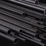
Generally, a tapered chuck is used to drill the outer circle. Since the graphite parts and chuck use an interference fit, the clamping force must be appropriate. Clamping of workpieces is shown in Figure 3. Generally, greater clamping force is used during rough grinding. This is because during the rough grinding process, the feed quantity is relatively large, the workpieces are pressed, and the grinding force on the workpieces is larger, so more clamping force is used. . Relative movement between workpiece and spindle can be avoided. When fine grinding, when there is no relative movement between the workpiece and the chuck, the lower the clamping force, the better to prevent the graphite workpieces from being stretched by the chuck and deformed elastically, thus affecting the size of the part. . The amount of interference during coarse grinding is generally 0.005-0.1mm, and the amount of interference during fine grinding is 0.003-0.005mm.

Figure 3 Tightening parts
4 Examples of processing graphite products
4.1 Examples of parts
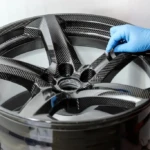
The material quality of the parts is M125P, which is characterized by light texture, low density and brittle material. The processing model requires that the coaxiality between the inner hole and the outer circle is 0.01 mm and the surface roughness value Ra = 0.8 μm. Processed with M1420A cylindrical grinder[4]according to RT 03 detection table to match the grinding size, calculate the gap value and fill it into RT-40 table, and use the through chuck during processing. The ground parts are shown in Figure 4.

Figure 4 Parts after grinding
4.2 Analysis of actual processing
The two machining marks for coaxiality are the inner hole of the part and the outer circle of the chuck. Chuck wear or poor contact between the tip and center hole can cause out-of-tolerance runout. The inner hole of the workpiece in the previous process is processed by a lathe. There may be clamping deformation, which may make the inner hole oval, thereby affecting the processing of the outer circle.
The elastic deformation of parts and the clamping force during clamping will affect the processing accuracy and cause measurement errors. The biggest processing difficulty lies in the surface roughness of the outer circle of graphite parts. Since graphite is a non-metallic material, the mixture of particles rejected by the grinding wheel and the cutting fluid will scratch the surface of the part; tiny impurities in the circulating cutting fluid rushing into the grinding zone will also cause passivation; of the grinding wheel will cause scratches on the surface of the workpiece. Multiple veins or spiral defects will appear.
4.3 Solutions
(1) The coaxiality of the parts ensures that the chuck is measured with a lever micrometer on the deflectometer before use. It can only be used when the runout of the outer circles at both ends of the chuck relative to the center hole is less. than 0.005 mm.
(2) The size of the parts ensures that the processing of the parts is divided into two parts: coarse grinding and fine grinding. Surface roughness and deformation are not taken into account during coarse grinding, and only the amount of grinding remaining for subsequent fine grinding is guaranteed. During processing, positioning plunge grinding is adopted, the cutting amount is relatively large, and the processing is carried out several times, and the feed amount is controlled at 0.01 ~ 0.02 mm/r. Slightly increase the clamping force between the workpieces and the chuck, with an interference of about 0.005~0.01mm, which can improve work efficiency. When fine grinding, measure the size of the workpiece first. If the workpiece is distorted, appears elliptical, or has a cylindricity greater than 0.01 mm, drill holes to ensure that the clamping force should be moderate and interference between the chuck and the. the workpiece should be controlled to 0.003~0.006mm, so that the elastic deformation of clamped parts is small and the geometric tolerance is guaranteed. When grinding, the machine tool adopts the reciprocating grinding method, and the feed speed is 0.001 ~ 0.005mm/r. The cutting amount is small, the grinding amount is small, and the pressure generated during grinding is used for a short time. time, allowing for a more precise grinding size. Reciprocating cutting can not only improve the surface quality of the outer circle, but also reduce the grinding marks produced on the machined surface of the workpiece, making the surface smoother.
(3) The surface roughness of the parts is guaranteed to ensure the surface roughness of the outer circle processed, mainly through the selection and dressing of the grinding wheel. When the hardness of the workpiece is low, the abrasive grains slowly passivate, causing the abrasive grains to fall off before they become dull, so a harder grinding wheel should be selected when the hardness of the workpiece is low and the toughness is high ; chips will easily clog the grinding wheel, so a coarse-grained grinding wheel should be selected with large pores. Combined with the soft nature of graphite, it is most effective to choose a chrome corundum grinding wheel with a hardness of K or L, a ceramic bond, and a grain size of 60#.
When fine grinding, grinding wheel wear is very low. Generally, a cut of 0.05 mm is enough to restore the cutting performance of the grinding wheel. The correction speed is slower, about 150~200mm/min. Finally, light pruning is carried out to remove individual protruding micro-edges and loose grains of sand on the grinding wheel.
(4) Cutting fluid When machining graphite parts, it is necessary to ensure that the cutting fluid is clean. The machine tool must be equipped with a filtration system to prevent the mixture of particles from falling from the grinding wheel and the cut. The fluid does not scratch the workpiece surface or mix tiny impurities into the circulating cutting fluid.
(5) Fixed value measurement: After the graphite parts are processed on the machine tool, a constant temperature adjustment is required. After the parts are stable, the measurement is then calculated according to the correspondence table and the table is carried out. completed.
5Conclusion
This article introduces the problems and solutions that arise in cylindrical grinding of graphite parts, summarizes and shares the grinding processing experience and skills. When processing graphite parts, it is necessary to carry out careful process analysis based on the material’s own characteristics and model requirements, and select appropriate fixtures, grinding wheels and grinding methods to solve problems such as clamping deformation, dimensional tolerances and surface defects of parts. Thus producing high quality products.
Expert Commentary
The graphite material in this example has excellent properties such as self-lubrication and corrosion resistance, and is widely used in the field of mechanical processing. However, graphite has a soft texture and is subject to elliptical deformation, dimensional deviations and surface quality defects during cylindrical grinding. Aiming at the quality problems that occur during cylindrical grinding of graphite parts, the author conducts analysis of causes and processing examples based on the characteristics of materials and parts, and summarizes the experience and skills of cylindrical grinding. By selecting appropriate grinding wheels and grinding methods, optimizing the spindle clamping method and other process improvement measures, problems such as clamping deformation, dimensional tolerances and surface scratches are solved efficiently, thereby improving production efficiency and reducing costs. The article has reasonable structure, complete content, clear logic and strong argumentation, and has good reference and application value.
Daguang focuses on providing solutions such as precision CNC machining services (3-axis, 4-axis, 5-axis machining), CNC milling, 3D printing and rapid prototyping services.