
Copper CNC Processing: How the Metal Behaves at the Cut
Copper CNC processing is not hard because the metal is hard. It is hard because the metal is soft, sticky and quick to move heat into the tool. This page explains what happens at the cut, which copper grades machine cleanly, and where the process stops being economical.
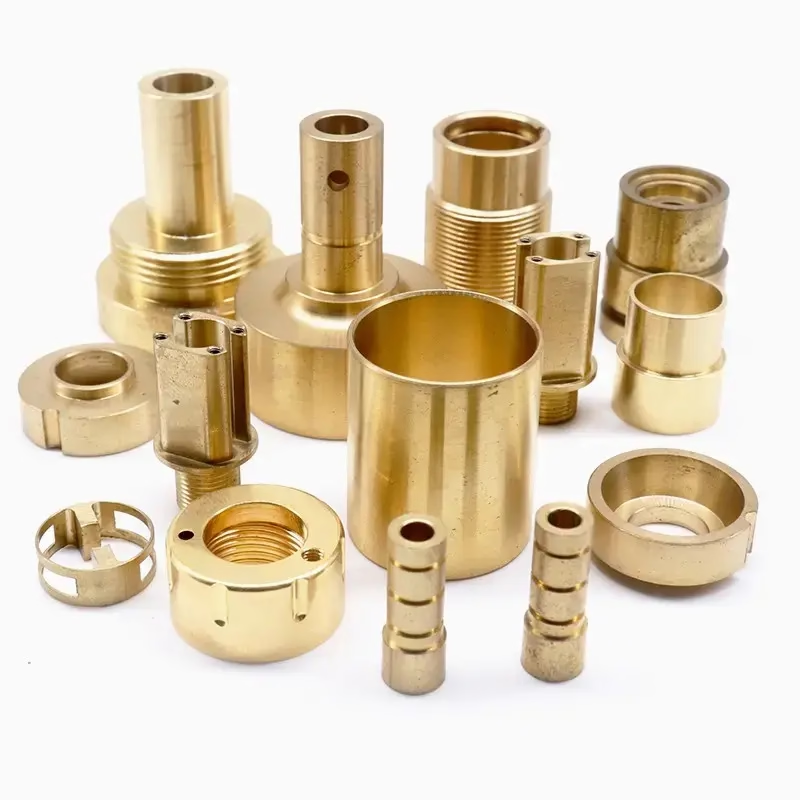
Why copper CNC processing behaves unlike steel
Copper sits at the opposite end of the machining spectrum from cast iron. It is soft, roughly 40–45 HV in annealed C110, yet it work-hardens fast under a dull edge. The chip does not shear and break the way a steel chip does. It stretches, rubs and welds to the rake face, then tears away in a lumpy, uncontrolled ribbon.
Thermal conductivity is the second half of the problem. Copper moves heat away from the cut zone about 10 times faster than 304 stainless. That sounds helpful, and partly it is. But the heat goes into the tool and the part instead of the chip, so the tool edge stays hot and the workpiece grows. A 100 mm copper block at 20 °C can move 0.15 mm in length after a 30 °C rise.
So the real difficulty is not cutting force. It is edge build-up and heat. A sharp, polished, high-rake tool takes a clean shear. A coated tool with a honed edge rubs, and rubbing turns into a built-up edge within a few seconds. Once that edge forms, surface finish collapses to Ra 3.2 μm or worse and the next pass cuts deeper than programmed.
Beryllium copper and high-purity oxygen-free grades push this further. They hold hardness better and machine closer to brass, but beryllium-bearing stock needs its own dust and coolant controls. That is a shop-floor decision, not a feed-and-speed decision.
Which copper alloys stay machinable
C110 (ETP) copper is the default for busbars, electrodes and heat sinks. It machines at 100–150 m/min with carbide, but it is gummy and needs sharp geometry and a strong coolant stream. Deep pockets and thin walls are where it fights back.
C101 and C103 oxygen-free copper are softer still and usually specified for vacuum or RF parts. They cut cleaner than C110 because there are no oxide inclusions to pull the edge, but they are more prone to smearing under a light finishing pass. Take a real depth of cut, 0.2–0.3 mm minimum, rather than a spring pass.
Brass is the easy branch of the family. C36000 free-cutting brass machines at 200–300 m/min with almost no built-up edge and gives Ra 0.8–1.6 μm straight off the tool. If a part does not need copper's conductivity, C36000 is almost always the cheaper route. C27400 and C28000 sit in between and behave closer to brass than to pure copper.
Beryllium copper (C17200 and similar) is the hardest of the group and the most stable dimensionally. It machines like a soft stainless, holds tight tolerances well, and is common in spring contacts, mold inserts and aerospace bushings. The trade-off is cost and handling, not machinability.
Where copper CNC processing stops paying off
Very thin copper is a poor fit for milling. Below about 0.8 mm wall thickness, cutting pressure bends the part before the tool cuts it cleanly. If a design calls for a 0.5 mm copper fin, expect to fixture it against a support, take light axial passes of 0.1–0.15 mm, and accept slower cycle times.
Feature size sets another boundary. Copper holds ±0.005 mm on a rigid setup, but thin ribs and sharp internal corners are where chatter appears first. A 0.4 mm end mill in copper needs a stub-length tool and a 0.05 mm radial stepover to survive; a longer tool will snap or wander.
Thermal growth is the last limit. On a 200 mm busbar with a ±0.02 mm hole pattern, a 10 °C shop swing is already a third of the tolerance. Rough, let the part cool, then finish. We measure copper after it returns to room temperature, not straight off the spindle.
Where the geometry is a flat plate with holes, laser cutting or waterjet is faster and cheaper. Copper CNC processing earns its place when the part needs pockets, threads, sealing faces, tight bores or a machined finish that a cut edge cannot give.
Speeds, feeds and the tool geometry that matters
Use uncoated carbide or a polished diamond-like coating for copper. TiAlN and similar hard coatings work against you here; the coating's own micro-roughness gives the chip something to weld onto. Two or three flutes with a 15–20° rake angle and a sharp, unhoned edge cut cleanest.
Rough with a real chip load. For a 10 mm three-flute end mill in C110, 0.08–0.12 mm per tooth at 3,000–4,000 rpm gives a thick enough chip to carry heat away. Light chiploads below 0.03 mm per tooth are the classic mistake: the tool rubs, work-hardens the surface and the next pass cuts into a hardened skin.
Coolant is not optional. A high-pressure flood or through-tool stream clears the soft chips before they recut. Copper fines pack into pockets and around the fixture, and recutting them destroys the finish. Air blast alone works on brass but not on pure copper.
Finishing passes should remove at least 0.15 mm radially. A spring pass at 0.02 mm looks safe and produces a torn, smeared surface every time. For Ra 0.2–0.8 μm on a sealing face, plan a separate finish operation with a fresh edge rather than pushing a worn tool to the end of the run.
Holding the part without deforming it
Copper dents. Standard steel vise jaws will mark a finished face under normal clamping force. Use soft aluminum or brass jaws, or clamp on a sacrificial tab that gets removed later. For thin plates, vacuum fixturing spreads the load and avoids jaw marks entirely.
Rough and finish in separate setups where the tolerance is tight. Roughing releases internal stress in rolled copper, and the part moves. Leave 0.3–0.5 mm of stock, stress-relieve or simply let it sit, then finish. This is the single biggest reason copper parts come back out of tolerance.
Support the underside. Copper deflects under axial load more than aluminum of the same section. For pockets deeper than 3× the tool diameter, step down in 0.2–0.3 mm axial passes with a stub tool, and keep the toolpath from cutting the full width in one engagement.
Measure at room temperature. Copper expands about 17 × 10⁻⁶ per °C. A part checked hot on the machine will read small and fail inspection later. We let finished parts stabilize before the final dimensional check.
Copper and brass grades at a glance
Ranges are starting points for carbide tooling with flood coolant.
| Grade | Machinability | Typical cutting speed | Best fit |
|---|---|---|---|
| C110 (ETP copper) | Gummy, prone to built-up edge | 100–150 m/min | Busbars, heat sinks, electrodes |
| C101 / C103 (OF copper) | Soft, clean cut, smears if too light | 120–180 m/min | RF parts, vacuum components |
| C17200 (beryllium copper) | Stable, holds tight limits | 60–100 m/min | Spring contacts, mold inserts |
| C36000 (free-cutting brass) | Excellent, minimal edge build-up | 200–300 m/min | Fittings, connectors, small parts |
| C27400 / C28000 (brass) | Good, slightly tougher than C36000 | 150–220 m/min | Valve bodies, decorative parts |
When copper is the right call
If the part needs conductivity, a sealing face or a tight bore, machine it from copper and budget for slower passes and soft jaws. If it only needs the shape, run it in C36000 brass or switch to sheet metal and save the cycle time.
Copper CNC processing questions
Can copper be machined to ±0.005 mm?
Yes, on a rigid setup with a sharp tool and temperature control. We hold ±0.005 mm (±0.0002 in) on copper bores, faces and hole patterns, with 100% inspection before shipment.
The practical limit is thermal, not mechanical. A 10 °C shop swing on a 200 mm part eats a large share of the tolerance, so roughing and finishing are separated and parts are measured at room temperature.
Why does copper give a poor surface finish?
Almost always built-up edge. A dull or coated edge welds copper to itself, then the lump tears off and leaves a smeared, torn surface. The usual fixes are a sharper uncoated tool, a higher rake angle and a real chip load.
A finishing pass that is too light makes it worse. Removing less than 0.15 mm radially rubs the surface instead of cutting it. Take a proper depth of cut with a fresh edge.
Is beryllium copper safe to machine?
It can be machined safely with the right controls. Beryllium-bearing dust and mist need local extraction and coolant management, and operators need the appropriate protection. It is a normal job for a shop set up for it.
On the machining side, beryllium copper is the most stable of the common copper alloys. It holds tight tolerances well and finishes cleanly, which is why it shows up in spring contacts and mold inserts.
What is the difference between C110 and C101 copper?
C110 is electrolytic tough pitch copper with a small oxygen content. C101 and C103 are oxygen-free, which matters for vacuum, RF and high-temperature service where oxide inclusions cause problems.
In the cut, oxygen-free grades are slightly softer and more prone to smearing. C110 is a touch more forgiving on the machine but carries oxide particles that can affect conductivity and vacuum performance.
Can copper parts be plated or finished after machining?
Yes. Electroless nickel, silver and gold plating are all common on copper, and each needs a clean, smeared-free surface to bond properly. Bead blasting, tumbling, brushing and polishing are also available.
For laser marking, plan for a minimum character height of 1.5 mm. Very fine text on copper fills in and reads poorly under a shop microscope.
How fast can copper parts ship?
Quotation and a free DFM analysis come back within 12 hours, and production can start within 24 hours. Typical parts ship in 3–5 days.
There is no minimum order quantity. One prototype and a 10,000-part run go through the same process, and uploads stay confidential with an NDA available on request.
Send us your copper part
Upload a STEP file and we will return a quote, a DFM analysis and a realistic cycle time within 12 hours.
12-hour quote100% inspectionNo minimum order
Follow GreatLight
We publish setup notes, tooling trials and inspection data from the factory floor.











