
cnc turning machiningglcncmachining: How a Single Point Cuts a Round Part
This page explains what happens inside a turning cycle, which features it holds tightly, and where the process runs out of room. It is written for design engineers and buyers who need to pick a process before they release a drawing.
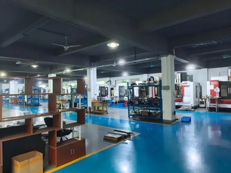
What happens inside one cnc turning machiningglcncmachining cycle
A lathe spins the workpiece. The tool stays still in X and Z and moves into the rotating surface. That is the whole idea, and it is why turning is the cheapest way to make anything round. The part is held in a chuck, a collet, or between centers. A 3-jaw chuck suits most work. A collet gives better runout on small bar stock. Centers carry long shafts that would otherwise deflect.
The cutting insert is a single point. It removes material along a helix as the part rotates and the tool feeds along Z. Feed is measured per revolution, not per minute, so chip thickness depends on spindle speed and feed rate together. Turning 6061 aluminium with a sharp uncoated insert at 600–900 m/min and 0.15 mm/rev leaves a clean chip and Ra 1.6 μm or better.
Heat leaves with the chip. That is the main reason turning holds size better than milling on the same material. The tool never rubs the finished surface for long, and the workpiece stays cool enough that thermal growth stays inside a few micrometres. On a Ø50 mm steel shaft, a 20 °C rise moves diameter by roughly 0.012 mm. Keep coolant on it and the number stops mattering.
Rough and finish passes are separate. A 2 mm depth of cut at 0.25 mm/rev removes stock fast. The finish pass then takes 0.2–0.5 mm at 0.05–0.1 mm/rev and sets the surface. Skip the light pass and you inherit the roughing marks plus the tool deflection that came with them.
Where turning stops being the right answer
Turning only reaches surfaces that are concentric with the spindle axis. A flat face perpendicular to the axis is easy. A slot across that same face needs a live tool or a second operation on a mill. This is the boundary most drawings cross without warning. If the feature does not rotate, turning cannot make it in the same setup.
Length-to-diameter ratio decides whether the part is stable. Up to 3:1, a chuck holds the part with no support. Between 3:1 and 6:1, a tailstock or steady rest is normal. Past 8:1, deflection and chatter dominate, and you either accept a slower cycle with light passes or move to a mill-turn center that supports the part differently.
Bar stock size sets the practical ceiling on a bar-fed machine. Parts above Ø80 mm usually move to a chuck. Our own work runs on 16 mill-turn centers and a Ø400 mm rotary table, with 4,000 mm maximum processing size for the long shafts that come out of aerospace and pump work. Above that envelope, the part gets split.
Thin walls behave badly. A 1 mm wall on a Ø60 mm aluminium cup will move under chuck pressure and again when the jaws release. Two fixes work: soft jaws bored to the finished diameter, or a light finish pass after the part is re-chucked with low clamping force. Both add a setup.
What ±0.005 mm actually demands
±0.005 mm is the tight end of normal turning, not the default. It is reachable on diameters up to about Ø100 mm in aluminium, brass, and free-machining stainless, provided the machine is warm, the tool is fresh, and the measurement is taken at 20 °C. On a long part or a hard material, the same callout is a coin flip.
Temperature is the first limit. Aluminium expands about 23 × 10⁻⁶ per °C. A Ø100 mm part checked at 25 °C reads roughly 0.011 mm larger than it will at 20 °C. That is more than the whole tolerance band. Either control the room or measure and correct.
Tool wear is the second. A carbide insert on 304 stainless wears 0.02–0.05 mm on the diameter over a few hundred parts. The operator compensates by offset, but that means the process needs in-process measurement, not just a first-article check. This is where 100% inspection before shipment earns its cost.
Surface finish and tolerance are linked. Getting Ra 0.2–0.8 μm usually needs a wiper insert or a burnishing pass, plus a feed under 0.08 mm/rev. If the drawing calls for both a tight diameter and a mirror finish, expect a slower cycle and a separate finishing tool.
How the part is held decides the result
Chuck jaws are not a precision fixture. A standard 3-jaw scroll chuck repeats to about 0.05 mm. A set of bored soft jaws brings that to 0.01 mm or better on the same diameter. For anything inside ±0.02 mm, soft jaws are the cheap answer and they take twenty minutes to make.
Collets are better on small bar. A 5C collet repeats to roughly 0.01 mm and grips evenly around the circumference, which matters on thin-wall tube. They only cover the size they were cut for, so a family of diameters needs a family of collets.
Between centers is the standard for shafts. A 60 ° center hole at each end, a drive dog, and a live center on the tailstock. Runout then depends on how well the center holes were made, not on the chuck. Drill and ream them in the same setup as the journal diameters and the part stays true.
Vibration shows up as a pattern on the surface, not as a size error. If a finish pass suddenly produces evenly spaced marks, the cause is usually a boring bar extended too far or a spindle speed sitting on a natural frequency. Change the speed by 10–15% before you change the tool.
Turning or milling: pick by feature
Match the process to the geometry, not to the material.
| Feature | CNC turning | CNC milling |
|---|---|---|
| Cylindrical OD / ID | First choice, one setup | Slow, needs a rotary table |
| Concentric grooves | Easy, single point | Hard to reach, special tool |
| Faces normal to axis | Easy | Easy |
| Slots across a face | Needs live tooling | Standard |
| Pockets and ribs | Not practical | Standard |
| Length : diameter > 8:1 | Needs steady rest | Better on a 4-axis mill |
| Ø100 mm, ±0.005 mm | Reachable when warm | Reachable, more setups |
| Thin wall under 1.5 mm | Soft jaws or collet | Better support from a fixture |
The short version
If the part is round and the features rotate, turn it. If more than a third of the features do not rotate, mill it or move to a mill-turn center and pay for one setup instead of three.
Questions that come up after the drawing
Can turning hold ±0.005 mm on a Ø200 mm part?
On a short, stiff part in aluminium or brass, yes, with a warm machine and a finish pass under 0.1 mm/rev. On a long part or in 316 stainless, the thermal and deflection budget eats the tolerance before the tool does.
The honest answer is that it depends on the length-to-diameter ratio more than the diameter. Send the drawing and we will say which side of the line it falls on.
Why does my turned part measure oversize after it cools?
The part grew during cutting and shrank on the bench. Aluminium at 25 °C reads about 0.011 mm larger on Ø100 mm than it does at 20 °C.
Measure at a controlled temperature, or machine to the corrected dimension. Do not chase the number with the offset while the part is still warm.
Do I need a mill-turn center or is a lathe enough?
A lathe is enough when every feature is concentric or on a face. A mill-turn center earns its cost when the part has cross holes, flats, or slots that would otherwise need a second fixture and a second setup.
One setup also means one datum, which usually removes a stack-up error from the tolerance chain.
What surface finish can a turning pass leave?
As-machined is Ra 1.6–3.2 μm. A normal finish pass with a wiper insert reaches Ra 0.8–1.6 μm. Ra 0.2–0.8 μm needs a light feed, a fresh insert, and often a burnishing pass.
If the drawing calls for Ra 0.2 μm across a long bore, check whether the function really needs it. That callout costs more than the tolerance.
How do I stop chatter on a long shaft?
Support it. A steady rest or tailstock takes the length-to-diameter ratio down to a range the tool can handle. Then drop the depth of cut and change the spindle speed by 10–15% to move off the resonant point.
If it still sings, the tool overhang is too long. Move the holder closer to the turret.
Does turning work for one-off prototypes?
Yes. There is no minimum order quantity here, so a single prototype and a 10,000-part run go on the same machines. Setup dominates the cost of a one-off, which is why soft jaws and collets are made once and kept.
For a first article, we quote and return a DFM analysis within 12 hours so you can fix the drawing before the chips fly.
Send the drawing, get a real answer
Quotation and free DFM analysis within 12 hours. No minimum order quantity, from one prototype to 10,000+ parts.
12-hour quote100% inspectionNDA on request
Follow GreatLight
We publish setup notes, tooling trials and inspection data from the factory floor.











