
CNC Precision Turning: How a Single Point Holds Your Tolerance
This page explains what happens at the cutting edge in CNC precision turning, which part features it handles well, and where the process runs out of room. It is written for design engineers and buyers who need to pick a process and defend the call.
In this article
- 1
- 2
- 3
- 4
- 5
- 6
- 7
- 8
- 9
- 10
Key takeaways
What CNC precision turning actually does at the cutting edge
Turning removes material with a single-point tool while the workpiece spins. The tool feeds along the Z axis for diameters and faces, and along X for depth of cut. Everything else in the machine exists to keep that one contact point in the right place: the spindle holds the part, the turret holds the tool, and the control follows the program.
That is why turning is so good at round features. A diameter is produced by one continuous motion, so size comes from the tool position rather than from a series of overlapping passes. Fewer passes means fewer chances to drift. On a stable setup, ±0.005 mm on a bore or journal is a normal working number, not a special request.
The contrast with milling matters. A mill cuts from the side with a rotating tool, so a round pocket or a boss arrives as an interpolation of many small moves. Turning produces the same shape in one sweep. For shaft-type parts, that difference shows up in cycle time, surface finish and how repeatable the size stays across a run.
CNC precision turning also covers boring, grooving, threading, parting and face work on the same machine. A part can be turned, threaded and cut off without a second operation. Each extra setup adds a new datum, and every datum is a place where error enters the stack.
- 1Single-point contactSize comes from tool position, not from averaging many cuts.
- 2Continuous motionA diameter is cut in one pass, so finish is uniform around the part.
- 3Multiple operations, one spindleTurning, boring, grooving and threading share the same datum.
Which part features belong on a lathe and which do not
The first question is not tolerance, it is shape. If the part is mostly a body of revolution and its critical features are coaxial, turning is the direct route. Shafts, bushings, pins, fittings, valve bodies, sensor housings and threaded connectors all fall into this group.
The second question is where the part stops being round. Cross holes, slots, flats, hex shapes and off-axis ports cannot be produced by a single-point tool feeding along the axis. They need a rotating tool. A lathe with live tooling or a mill-turn center can do them in the same setup, which is often cheaper than moving the part to a mill.
The third question is length-to-diameter ratio. A part that is short and stiff cuts clean. A shaft that hangs far out of the chuck will deflect under cutting force, and the measured size will vary along its length. Steady rests, tailstocks and a lighter finishing pass are the usual answers, but they add time.
Parts that are mostly flat, thin-walled or pocketed on several faces are better handled by milling or 5-axis work. Forcing them onto a lathe means adding fixtures and live tooling to fight the geometry, and the setup cost usually wins out.
- 1Good fitCoaxial diameters, bores, faces, threads, grooves, chamfers.
- 2Possible with live toolingCross holes, flats, slots, hex features, off-axis ports.
- 3Poor fitLarge flat plates, deep pockets on multiple faces, thin walls.
What sets the achievable tolerance in CNC precision turning
Tolerance is a system result, not a machine brochure number. The control, the spindle, the tool holder and the workpiece all contribute. Thermal growth is part of it: a spindle that has been running for hours sits at a different length than one that started cold, and that shift lands directly on the diameter.
Tool wear is the second factor. A turning insert wears on the flank as it cuts, so the effective cutting edge moves and the diameter creeps. On a long run the operator compensates, usually by adjusting the offset at fixed intervals. The interval depends on the material and the insert grade, not on a fixed rule.
Workpiece stiffness is the third. Any deflection under cutting force is recovered when the tool passes, so the part springs back and the cut is shallower than commanded. This is why a finishing pass with a small depth of cut often holds a tighter number than a heavy roughing pass on the same machine.
Measurement closes the loop. A part that is checked with a micrometer at one temperature and assembled at another will not measure the same. For tight work, we measure at the machine, note the temperature, and report the result with the inspection record so the number can be interpreted later.
- 1Thermal driftSpindle growth shifts the diameter over a long run.
- 2Insert wearFlank wear moves the edge; offsets are adjusted on a schedule.
- 3DeflectionLight finishing passes hold tighter than heavy roughing.
Why one setup decides concentricity more than any tolerance callout
Concentricity and runout are relationship tolerances. They describe how one feature sits relative to another, so they depend on how many times the part was gripped. Two bores machined in the same chucking share a spindle axis. The same two bores machined in two operations share a fixture and an operator's dial indicator instead.
This is the main argument for mill-turn and 5-axis centers. The part is gripped once, turned on the main spindle, then picked up by the counter spindle or rotated on a trunnion for the remaining features. Datum transfer disappears because there is no second datum.
The trade-off is programming and cycle time. A single-setup job on a mill-turn center takes longer to prepare and often runs slower than two simple operations on separate machines. For a prototype or a tight-tolerance part, the setup saving usually wins. For a loose-tolerance part in high volume, splitting the work across cheap machines can be the better economic call.
Another practical point: a single setup also removes handling. Every time a part is unloaded, moved and reloaded, it can be dropped, dinged or contaminated with chips. Fewer touches means fewer rejects, and that effect is often larger than the tolerance gain itself.
- 1Relationship tolerancesConcentricity and runout depend on how many times the part was gripped.
- 2Mill-turn advantageOne grip, one datum, no re-indication between features.
- 3Cost trade-offSingle setup costs more to program but removes datum error and handling.
Material behavior that changes the turning setup
Aluminium 6061 and 7075 cut freely and hold a good finish. They also move with heat, so a heavy roughing pass can warm the part enough to shift the finishing cut. On tight aluminium work we rough, let the part settle and finish.
Stainless 303 is the free-machining grade and behaves well. Grades 304, 316 and 17-4PH work-harden if the tool rubs instead of cutting, so a positive rake and a feed that stays under the hardened layer matter more than spindle speed alone.
Titanium TC4 (Ti-6Al-4V) and Inconel generate heat at the edge and conduct it poorly. The tool takes the heat, so insert life is short and speeds stay low. These grades are workable but they need realistic cycle times and a rigid setup.
Copper, brass and beryllium copper cut easily and produce a fine finish, though they are abrasive on the tool and gummy on deep cuts. Plastics such as POM, PEEK and PA need sharp edges and good chip evacuation, because a melted chip welded to the tool will score the surface.
- 1AluminiumFree cutting but thermally active; rough and finish separately.
- 2Stainless and 17-4PHWork-harden if the tool rubs; keep the edge cutting.
- 3Titanium and InconelHeat stays in the tool; lower speeds, shorter insert life.
Surface finish, edge breaks and the cost of a finer number
Finish on a turned surface is largely set by feed per revolution and tool nose radius. A larger nose radius or a finer feed lowers Ra, but both slow the cycle. Ra 1.6–3.2 μm is a normal as-machined result, Ra 0.8–1.6 μm is a controlled finishing pass, and Ra 0.2–0.8 μm needs a fine pass with a sharp insert and stable chip control.
Grinding is the usual route when a turned surface cannot reach the number. It adds a step, a new setup and a new datum, so it should be a deliberate choice rather than a default. For most sealing and bearing surfaces, a well-controlled turning pass is enough.
Edge breaks are a separate decision from finish. A sharp corner on a turned part is a stress riser and a handling hazard. A small chamfer or radius costs almost nothing at the machine and removes both problems. Laser marking for part numbers needs a minimum character height of 1.5 mm to stay legible after finishing.
Anodizing, plating, black oxide and bead blasting all change the final dimension slightly. If a coating is planned, say so before the part is machined, because the pre-plate size has to be adjusted to leave the right final dimension.
- 1Finish comes from feedLower feed per revolution and a larger nose radius reduce Ra.
- 2Grinding is a choiceIt reaches the finest numbers but adds a setup and a datum.
- 3Plan for coatingsAnodizing and plating shift the final size; adjust the pre-plate dimension.
From drawing to inspected part in a short run
A turning job starts with a DFM check. We look at wall thickness, tool reach, thread depth and whether the tolerances can be held in the planned number of setups. The quotation and the DFM notes come back within 12 hours, and production can start within 24 hours once the drawing is released.
First-article inspection confirms the setup before the run continues. Material certificates are checked on arrival, the process is monitored during cutting, and every part is inspected before shipment. Inspection reports are available on request.
Typical runs ship in 3–5 days. There is no minimum order quantity, so a single prototype and a 10,000-part run follow the same route. Uploads stay confidential and an NDA is available on request.
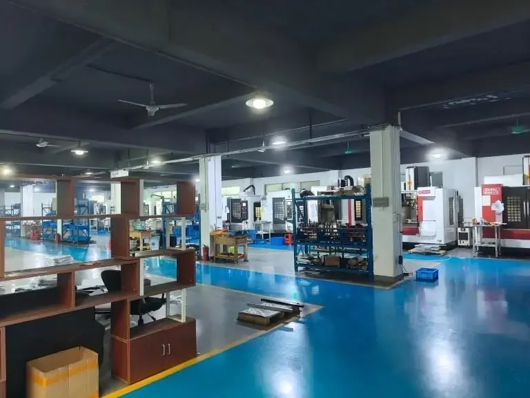
For parts that mix turning with milling features, the shop runs 127 high-precision CNC machines, including 16 mill-turn centers and 16 simultaneous 5-axis machining centers, with a maximum processing size of 4,000 mm. That range covers most turned parts without sending them out.
- 1DFM firstWall thickness, tool reach and setup count are checked before quoting.
- 2InspectionFirst article, in-process monitoring and 100% inspection before shipment.
- 3No minimumOne prototype or a 10,000-part run, same process route.
Turning a part in five process steps
The order matters more than the individual numbers.
- 1Fix the datumChoose the face and diameter that locate every other feature, and grip there first.
- 2Rough with stock leftLeave 0.3–0.5 mm on diameters for the finishing pass so thermal movement is cut away.
- 3Let the part settleA short pause or a coolant soak before finishing reduces size drift on tight work.
- 4Finish at a light depthTake 0.1–0.2 mm at a fine feed to hit Ra 0.8–1.6 μm and the final size.
- 5Break edges and inspectAdd chamfers, then measure at the machine and record the result.
CNC precision turning against the alternatives
Use this table to pick a route before you ask for a quote.
| Route | Best for | Watch out for |
|---|---|---|
| 2-axis turning | Shafts, pins, bushings, threaded fittings | Off-axis holes need a second operation |
| Turning with live tooling | Turned parts with cross holes or flats | Tool clearance limits feature positions |
| Mill-turn center | One-grip parts with tight concentricity | Higher programming and hourly cost |
| 5-axis machining | Complex geometry, angled faces, impellers | Not the cheapest route for simple round parts |
| Milling only | Plates, pockets, thin walls, prismatic bodies | Round features come from interpolation |
| Grinding after turning | Hardened parts, Ra below 0.2 μm demands | Adds a process step and a new setup |
When to choose turning and when to choose something else
If the critical features are coaxial and round, CNC precision turning in one or two setups is the cheapest way to hold the tolerance. If the part is prismatic, thin-walled or pocketed on several faces, milling or 5-axis is the honest answer, and a mill-turn center only pays off when one-grip concentricity is worth the hourly rate.
Questions engineers ask before releasing a turning job
Can you hold ±0.005 mm on a long shaft?
It depends on the length-to-diameter ratio, not on the tolerance alone. A short, stiff shaft holds ±0.005 mm in a normal setup.
A long shaft needs a tailstock or steady rest, and even then the size may vary along its length. Send the drawing and we will say which case yours is.
Do I need a mill-turn center for a part with cross holes?
Not always. A lathe with live tooling can drill cross holes and cut flats if the positions are reachable and the tool has clearance.
A mill-turn center becomes the better choice when the cross features are tight relative to the turned diameters, because the part stays in one grip.
Which materials are a problem on a lathe?
Nothing common is impossible, but titanium and Inconel are slow and hard on inserts, so cycle times and tool cost go up.
Plastics machine well with sharp tooling but need good chip evacuation. A melted chip welded to the edge will score the surface.
How do coatings affect the final dimension?
Anodizing, plating and black oxide all add or remove a small amount of material. If a coating is specified, the pre-plate size has to be adjusted.
Tell us the finish before machining starts so the turning program can leave the right allowance.
What is the smallest quantity you will run?
There is no minimum order quantity. One prototype and a 10,000-part run go through the same process route.
For a single part, the setup dominates the cost, so the DFM notes are worth reading before you release the drawing.
How is inspection documented?
Material is checked on arrival, the process is monitored during cutting, and every part is inspected before shipment.
Reports are available on request. For tight work we record the measurement temperature so the number can be interpreted later.
Send a turning drawing and get DFM notes back
Quotation and free DFM analysis within 12 hours. No minimum order quantity, from one prototype to a 10,000-part run, with 100% inspection before shipment.
12-hour quote100% inspectionNo minimum order quantity
More from the shop floor
We publish setup notes, tooling trials and inspection data from the factory floor.











