
CNC Precision Turning Components: How They Are Made and Where They Fit
This page explains the mechanics behind CNC precision turning components: how metal is removed on a lathe, where the process holds ±0.005 mm and where it does not, and which part shapes belong on a turning center instead of a mill. Written for design engineers and buyers who need to judge a print before sending it out for quote.
In this article
- 1
- 2
- 3
- 4
- 5
- 6
What actually happens inside a turning center
Turning is a single-point cutting process. The workpiece spins; the tool stays mostly still and feeds along the part axis. That one difference from milling decides almost everything downstream. Because the part rotates, every feature cut in the same setup shares one centerline. Diameters, shoulders, grooves and threads all inherit the spindle's runout rather than the machine's squareness in three axes.
The cutting edge removes material in a continuous chip at a set surface speed and feed per revolution. Surface speed is measured at the diameter being cut, so a facing pass on a Ø120 mm bar starts fast and slows as the tool reaches center. Feed, by contrast, is programmed per revolution, not per minute. Two machines running the same program at different spindle speeds will produce the same chip load only if the feed rate is recalculated.
Heat leaves with the chip, which is why turning handles deep cuts in tough alloys better than many people expect. The trade-off is deflection. A slender part pushed by a radial cutting force bends away from the tool, so the tool cuts less than programmed. The result is a barrel-shaped diameter: undersized in the middle, on size at the ends where the chuck and tailstock support the work.
Tolerances follow from this geometry. On a rigid, well-supported part, a CNC lathe holds ±0.005 mm routinely. Stretch that same part past roughly 4:1 length-to-diameter without a steady rest, and you are negotiating with physics, not with the machine's spec sheet.
- 1One setup, one centerlineConcentricity between turned features usually beats what milling can hold across setups.
- 2Feed is per revolutionChip load stays constant only if surface speed and feed are matched to the diameter.
- 3Chip carries the heatCoolant matters most for finish and tool life, less for dimensional control.
Which part shapes suit CNC precision turning components
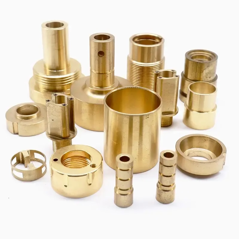
If the part is round or nearly round, turning is usually the cheaper route. Shafts, spools, bushings, pins, valve bodies, connector shells, hydraulic fittings and threaded studs all fall into this group. Any feature that can be described as a diameter, a face, a groove or a thread is native to the lathe.
Live tooling changes the boundary. A mill-turn center can drive an end mill or drill off-axis while the part rotates, so cross-holes, flats and slots get cut without a second operation. That removes one setup and one chance for a locating error. It does not turn the machine into a 5-axis mill. Reach is limited by the turret, and deep pockets or long compound angles still belong on a machining center.
Parts that are mostly prismatic are a poor fit. A rectangular housing with four bored holes is a milling job with a turning feature, not the reverse. So is anything with thin walls in more than one plane, where chuck pressure will distort the blank before the tool touches it.
Size sets another limit. GreatLight runs a Ø400 mm rotary table and up to 4,000 mm of processing length on the larger machines, with compact travels of 500 × 500 × 450 mm and 500 × 310 × 200 mm on the small lathes. Long, thin parts and very short, large-diameter rings pull the process in opposite directions. Talk to the shop before assuming either one is routine.
- 1Good fitShafts, bushings, fittings, valve bodies, threaded parts, connector shells.
- 2BorderlineCross-drilled round parts, which may need live tooling or a second op.
- 3Poor fitPrismatic housings, deep pockets, thin walls in multiple planes.
How material choice changes the cut
Aluminum is the easy case. Grades like 6061-T6 and 7075 cut at high surface speed, throw a clean chip and hold tight tolerances with little fuss. 6061-T6 machines better than 6061 in the annealed condition because it is harder and less gummy. The aluminum family at GreatLight runs from 2024 and 5052 through 6082 and ADC12.
Stainless is where setups get tested. Austenitic grades 303, 304 and 316L work-harden at the cut. If the tool rubs instead of cutting, the surface gets harder, the next pass rubs more, and the finish degrades fast. The fix is aggressive feed and a sharp edge, never a lighter pass. Grade 303 with its added sulfur machines noticeably better than 304 and is the usual pick when corrosion resistance is adequate.
Steel and titanium take the opposite approach: slower surface speed, heavier chip load, rigid support. Ti-6Al-4V (TC4) has low thermal conductivity, so heat concentrates at the edge. Tool life drops, and the part may need a spring pass to control diameter after the first cut releases residual stress. Inconel behaves similarly but worse.
Copper and brass sit between the two. C36000 free-cutting brass produces a short chip and excellent finish. Pure copper C101 and C110 are soft and sticky, so they tear unless the tool is very sharp and the feed is high enough to keep the edge buried. Plastics such as POM, PEEK and PA need sharp, polished tools and generous clearance, because a dull edge pushes the material instead of shearing it.
- 1AluminumHigh speed, light chip load, easy tolerance control.
- 2StainlessNever rub. Light passes work-harden the surface and ruin the finish.
- 3Titanium and InconelLow speed, heavy feed, expect tool wear and a possible spring pass.
Setup, fixturing and how tolerance is actually held
A turned part is only as good as its workholding. A three-jaw chuck is fast but repeats to roughly 0.05 mm unless the jaws are bored in place. A collet holds better and grips evenly, which matters for thin-walled parts. Between centers with a face driver gives the best concentricity on shaft-type work and leaves both ends open for machining.
Chatter is the most common cause of a failed first article. It shows up as a regular pattern on the surface and a wandering diameter. The usual causes are too much tool overhang, too little support, or a spindle speed that happens to match a natural frequency of the setup. Changing speed by 10 to 15 percent often kills it. Adding a steady rest or shortening the tool holder does the rest.
Thermal drift is quieter and more dangerous. A machine that has been sitting cold will grow as the spindle warms, and the first twenty parts of a shift can drift outside tolerance while the program stays the same. Production runs at GreatLight start after a warm-up cycle for this reason.
Inspection closes the loop. A turned diameter is measured with a micrometer or a bench comparator, not calipers, once the tolerance is below about 0.02 mm. GreatLight runs raw material checks, in-process monitoring and a final inspection on 100 percent of parts before shipment, with reports available on request. A 99.99 percent qualification rate is the target across those checks.
- 1Collet over three-jawBetter concentricity and even grip, especially on thin walls.
- 2Speed change beats dampingA 10–15 percent rpm shift often clears chatter without new tooling.
- 3Warm up before productionThermal growth moves diameters even when the program does not change.
Where the cost sits in a turned part
For a single prototype, the part price is mostly programming and setup. The cut itself may take four minutes. That is why a quote for one piece looks high next to a quote for five hundred, and why the same geometry can drop steeply once a fixture exists and the program is proven.
At low volume, material is the second cost driver. A part cut from Ø50 mm bar when Ø38 mm would do wastes both stock and cycle time, because the tool has to remove the difference. Specifying the nearest standard bar size is one of the simplest ways to cut cost on a turned component.
At high volume, cycle time dominates. Every extra feature adds turret index time and tool changes. Features that could be formed in the same pass, such as a chamfer and a face, should be combined in the drawing intent rather than split across operations. Free-cutting grades such as 303 stainless or C36000 brass pay for themselves in cycle time once annual volume is meaningful.
Surface finish is its own line item. Ra 1.6–3.2 μm comes straight off a normal turning pass. Getting to Ra 0.8–1.6 μm usually means a finishing pass with a wiper insert. Ra 0.2–0.8 μm may need a separate finishing operation, a different tool, or a secondary process such as tumbling or polishing. Specify the finish the function needs, not the finest number available.
- 1Low volumeSetup and programming dominate; material size is second.
- 2High volumeCycle time dominates; combine features into single passes.
- 3FinishEach finer Ra band adds a pass or a secondary operation.
Turning, mill-turn, or milling: picking the right process
Match the part shape to the process before arguing about tolerance.
| Part feature | Best process | Typical hold | Watch out for |
|---|---|---|---|
| Shaft or bushing, round throughout | CNC turning | ±0.005 mm | Deflection past 4:1 L:D |
| Round part with cross-holes or flats | Mill-turn center | ±0.01 mm | Turret reach limits |
| Prismatic housing with bores | 3-axis or 5-axis milling | ±0.01 mm | Extra setup for bores |
| Thin-wall tube, OD and ID | Turning with collet | ±0.01 mm | Chuck and cutting pressure |
| Threaded fitting, high volume | Turning, bar feeder | ±0.01 mm | Chip nesting in threads |
| Large ring, short length | Turning, soft jaws | ±0.01 mm | Out-of-round after release |
| Prototype, complex angles | 5-axis machining | ±0.005 mm | Programming and setup time |
When turning is the right call
If the part is round and most of its features rotate around one axis, turn it: you get ±0.005 mm and a fine finish from a single setup. If the part is mostly prismatic, or the walls are thin in more than one plane, put it on a mill. Mill-turn sits in between and is worth the extra cost only when cross-features would otherwise force a second setup.
Questions engineers ask before quoting
How tight a tolerance can CNC turning actually hold?
On a rigid setup with good support, ±0.005 mm is routine and is what GreatLight quotes as standard capability. The limiting factor is usually the part, not the machine. Once length-to-diameter passes roughly 4:1 without a steady rest, deflection takes over and the achievable tolerance loosens.
Very tight tolerances also cost money in inspection, not just machining. Below about 0.02 mm you need a controlled-temperature room and micrometers or a comparator rather than calipers, and the measurement becomes a real part of the cycle time.
What is the smallest and largest part you can turn?
Machine travels at GreatLight cover compact lathes at 500 × 500 × 450 mm and 500 × 310 × 200 mm, medium machines at 750 × 1,150 × 550 mm and 600 × 600 × 600 mm, and larger work up to a 4,000 mm processing length on a Ø400 mm rotary table.
Small diameter bar work is limited less by the machine than by the bar feeder and the rigidity of the stock. Very slender parts need a guide bushing or a steady rest, which changes the setup and the price.
Do you deburr turned parts and how are threads checked?
Parts come off the machine with edges broken unless the drawing calls for a sharp edge, and deburring is part of the finishing step. Threads are checked with go/no-go gauges when the drawing specifies a class, and with thread micrometers for diameter and pitch when it does not.
Laser marking is available for part numbers and lot codes. Minimum character height is 1.5 mm, so plan the mark area accordingly.
Which materials are hard to turn and what changes?
Titanium grades such as TC4, Inconel and austenitic stainless 304 and 316L are the difficult group. They work-harden or hold heat at the cutting edge, so the shop slows surface speed, increases feed and accepts shorter tool life.
Soft, sticky materials are difficult in a different way. Copper C101 and C110 tear easily and need very sharp tooling and a high feed to keep the edge engaged. POM and PEEK need polished tools and generous clearance to avoid pushing the material instead of cutting it.
Can turned parts be finished and assembled in the same order?
Yes. Anodizing, plating, powder coating, black oxide, bead blasting and polishing are all available as follow-on steps, and laser marking can be added after finishing. Finishing after machining matters because anodizing and plating add a small, predictable thickness that can move a diameter.
If a diameter has to mate after plating, tell us the final dimension and we will adjust the pre-plate size. Otherwise a tight bore may not accept its mating pin.
How do I get a quote and how fast?
Upload the drawings or 3D files through the online quotation page. Quotation and a free DFM analysis come back within 12 hours, and production can start within 24 hours of approval. There is no minimum order quantity, so a single prototype and a 10,000-part run go through the same route.
Uploads are secure and confidential, and an NDA is available on request. If the print has a feature that will be expensive or impossible, the DFM note will say so before you commit to tooling.
Send the print, get a turning plan
Upload your drawing and we will come back within 12 hours with a quote and a DFM note on the features that affect cycle time.
12-hour quote100% inspectionNo minimum order
More from the shop floor
We publish setup notes, tooling trials and inspection data from the factory floor.











