
CNC Precision Turning Parts: How Single-Point Cutting Holds ±0.005 mm
This page explains the mechanics behind CNC precision turning parts, the geometry that suits a lathe, and where the process stops working. Written for design engineers and buyers who need to decide between turning, milling, and mill-turn before releasing a drawing.
In this article
- 1
- 2
- 3
- 4
- 5
- 6
- 7
What happens where the tool meets the part
Turning removes material with one continuous cutting edge while the workpiece spins. The tool feeds along X and Z, so the surface you get is a helix, not a series of overlapping passes. That single-point geometry is why turning holds diameter and roundness so well: the tool never leaves the cut, so there is no re-entry mark.
The cutting edge sits at a fixed radius from the spindle axis. Radial forces push the tool away from the work, and that deflection is the largest single error source on a lathe. On a 50 mm diameter shaft in 4140 steel, a 0.2 mm depth of cut at 0.15 mm/rev produces enough radial load to move the tool 3–8 μm depending on overhang. Tool nose radius and edge honing change that number.
Heat leaves with the chip, not the part. In aluminum and brass, 70–80% of cutting heat exits in the chip, which keeps thermal growth of the workpiece low. Titanium and Inconel invert that ratio. The part grows during the pass and shrinks after, so a diameter measured warm can read 10–15 μm oversize once it cools.
Surface finish follows feed rate, not spindle speed, in the normal range. A 0.8 mm nose radius at 0.1 mm/rev gives a theoretical Ra around 0.4 μm. Push the feed to 0.3 mm/rev and the same tool produces roughly Ra 3 μm. That is the lever most programmers use to hit Ra 0.8–1.6 μm without a second operation.
- 1Tool deflectionLargest error source; grows with overhang and depth of cut
- 2Thermal growthBites hardest in titanium and nickel alloys
- 3Feed rateSets finish; spindle speed sets tool life
Which part shapes belong on a lathe
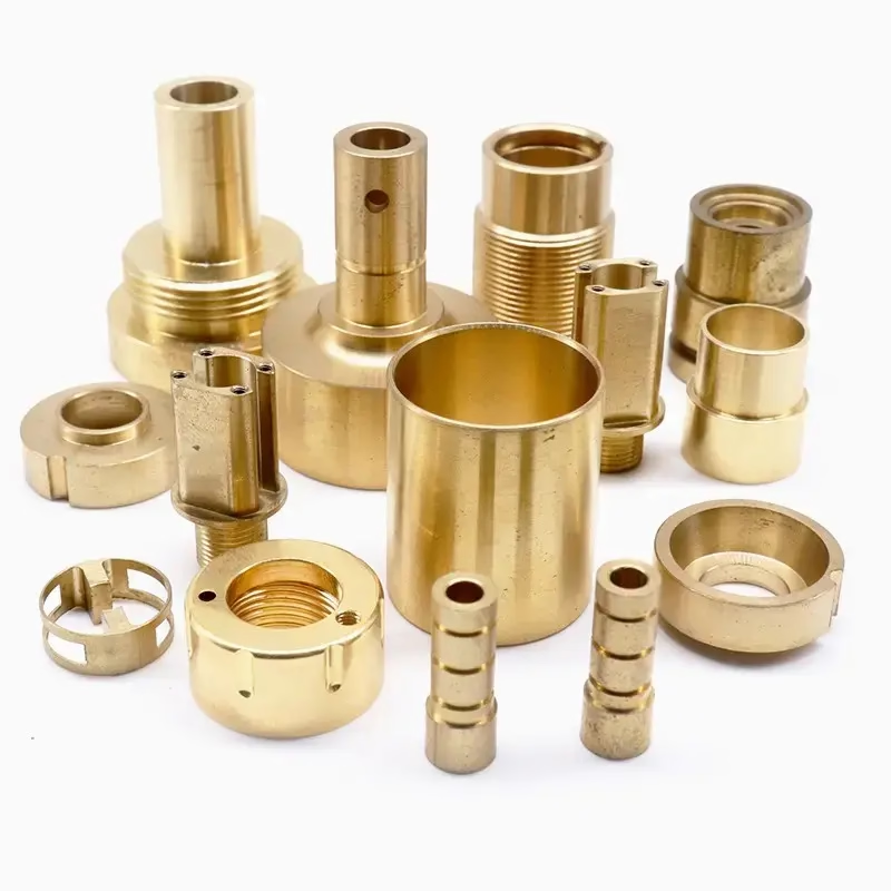
A turned part is a solid of revolution. If you can describe the shape by sweeping a 2D profile around a centerline, turning is the cheaper route. Shafts, bushings, spacers, threaded studs, valve bodies, fittings, and pistons all fall into this group. The more of the part that is rotationally symmetric, the less secondary work you pay for.
The ratio of length to diameter decides how hard the job is. Up to 3:1, a chuck holds the part with no support and you can hold ±0.005 mm without drama. Between 3:1 and 6:1, a tailstock or steady rest becomes necessary. Beyond roughly 10:1, deflection and chatter take over and you should expect to grind or rethink the design.
Feature orientation matters more than overall shape. Cross holes, flats, slots, and keyways are not turned features. They need a second setup on a mill, or a live tool on a mill-turn center. Each extra setup adds locating error, typically 10–20 μm between operations, which eats into your tolerance budget.
Undercuts, sharp internal corners, and deep bores fight the tool. A standard turning insert has a nose radius between 0.2 mm and 1.2 mm, and that radius cannot cut a sharper internal corner. If your drawing calls for a 0.1 mm corner radius at the bottom of a bore, the tool will leave a fillet or the programmer will reach for a grooving bar and add cycle time.
- 1Good fitShafts, bushings, fittings, threaded parts, valve seats
- 2Needs a second opCross holes, flats, slots, off-axis ports
- 3Corner radius floorSet by the smallest available insert nose radius
Chucking, workholding, and how errors enter
A three-jaw chuck is fast but not concentric. Jaw wear and scroll error put the part 10–30 μm off the spindle axis on a used chuck. For parts that need true concentricity between two diameters, a collet or a soft jaw bored in place is the better choice. A bored soft jaw can hold 5 μm runout on the same diameter it was bored to.
The second operation is where most tolerance is lost. When you flip a part to machine the back face, the new zero point depends on how well the part sits in the jaws. Saw-cut ends, burrs, and chamfer variation all shift that datum. It is common to see a ±0.02 mm true position callout on a cross hole fail not because the mill is inaccurate but because the flip was inconsistent.
Mill-turn centers remove the flip. With 16 mill-turn centers on our floor, a part can be turned, cross-drilled, and slotted in one clamping. That keeps concentricity between the turned diameter and the milled feature inside ±0.005 mm, because there is no re-datum. The tradeoff is setup time and tool cost, which only pays back once the geometry actually needs both processes.
Bar feeders help on high-volume work. A 10,000-part run of small stainless fittings runs unattended overnight and holds size because the bar stock feeds at a constant rate and the tool wears predictably. On a one-off prototype, the same setup takes longer to prepare than to cut.
- 1Three-jaw chuckFast, 10–30 μm runout on a worn chuck
- 2Bored soft jawsAround 5 μm runout on the bored diameter
- 3Mill-turnOne clamping, no re-datum, higher setup cost
Material behavior on the lathe
Aluminum 6061-T6 turns clean and fast, but it is gummy at low speed and builds a built-up edge that ruins finish. Run it above 300 m/min with sharp, polished inserts and a high rake angle. 7075 cuts cleaner and holds a better finish, but it is more prone to stress relief movement after roughing, so leave 0.3–0.5 mm for a finish pass on thin walls.
Stainless 303 is the free-machining grade and the default for turned fittings. 304 and 316 work-harden fast; if the tool rubs instead of cutting, the surface hardens and the next pass breaks the insert. Keep the feed per revolution high enough to stay under the hardened layer, typically 0.1 mm/rev or more, and never dwell in the cut.
Titanium Ti-6Al-4V and Inconel cut at 30–60 m/min with carbide, with high pressure coolant aimed at the edge. Both hold heat in the part, so rough, cool, then finish. If you measure immediately after the finish pass, the part will read oversize; let it stabilize first.
Brass C36000 and copper C110 turn easily but grab the tool. Brass chips are short and clear fast. Copper is ductile, produces long stringy chips, and needs a chipbreaker and peck-style feed changes. Beryllium copper adds a health-and-safety step in chip handling, which is worth knowing before you specify it.
- 1AluminumHigh speed, sharp polished inserts, watch built-up edge
- 2Stainless 304/316Feed hard, never rub, avoid dwelling in the cut
- 3Ti and InconelLow speed, high pressure coolant, let the part cool before measuring
Where turning stops being the right answer
Prismatic parts with no axis of symmetry should go straight to a mill. A bracket, a plate with a bolt pattern, or a housing with parallel faces has nothing for a lathe to reference. Trying to turn it means fixturing that costs more than the milling operation it avoids.
Very tight flatness and parallelism on a shoulder face are hard on a lathe. A faced shoulder is normally flat to 10–20 μm across a 100 mm diameter because the tool sweeps a helix and the spindle has some axial float. If your drawing calls for 5 μm flatness across that face, plan for a surface grind after turning.
Thin-wall tubes below 1 mm wall thickness deflect under chuck pressure. Options are a expanding mandrel, a pie jaw, or filling the bore with low-melt alloy. All of them add cost. If the wall can be 1.5 mm instead of 0.8 mm, the part gets cheaper and no less functional in most cases.
Hardened material above 45 HRC is usually turned before heat treat and ground after. Turning hard stock directly needs ceramic or CBN inserts, and even then the surface integrity is harder to control than grinding. For a bearing seat, the sequence is turn, heat treat, grind.
- 1Prismatic geometryGo to milling; no rotational reference exists
- 2Tight shoulder flatnessUnder 10 μm across a large face usually means grinding
- 3Thin wallsUnder 1 mm needs mandrel or low-melt support
- 4Hard materialAbove 45 HRC, turn soft then grind after heat treat
Reading a tolerance callout against the process
A diameter tolerance of ±0.005 mm is achievable on a rigid setup with a warm machine, but it is not free. It requires a finish pass with a light depth of cut, in-process gauging, and often a temperature-controlled room. If the function allows ±0.02 mm, say so; the part gets cheaper and ships faster.
Geometric callouts matter more than the size tolerance on many turned parts. Circularity and cylindricity depend on spindle condition and tool wear, not on the operator's skill. A machine that holds ±0.005 mm on diameter can still show 8 μm circularity if the spindle bearings are worn. When circularity drives function, call it out explicitly instead of assuming the diameter tolerance covers it.
Surface finish interacts with tolerance. A Ra 0.2–0.8 μm finish needs a wiper insert or a slow finish pass, and both raise cycle time. On a sealing surface, that cost is justified. On a non-contact outer diameter, Ra 1.6–3.2 μm is fine and cuts minutes off the cycle.
Measurement is part of the tolerance. A micrometer reads diameter at one point. A CMM or a roundness tester reads the whole surface. If your inspection plan uses different instruments than the supplier's, agree on the method before the first article, not after parts arrive.
- 1Size vs formDiameter tolerance does not imply roundness
- 2Finish costRa 0.2–0.8 μm needs wiper inserts or slow passes
- 3Method firstAgree on the gauging method before first article
Turning, milling, and mill-turn compared
Use this to pick a process before you release the drawing.
| Criterion | CNC turning | CNC milling | Mill-turn |
|---|---|---|---|
| Part shape | Solid of revolution | Prismatic, multi-face | Both in one part |
| Typical tolerance | ±0.005 mm on diameter | ±0.01 mm on features | ±0.005 mm across features |
| Cross holes | Second setup or live tool | Native | Native, no re-datum |
| Setup count | 1–2 | 1–3 | 1 |
| Finish capability | Ra 0.2–0.8 μm on OD/ID | Ra 0.8–1.6 μm typical | Ra 0.8–1.6 μm both sides |
| Best volume | 1 pc to 10,000+ | 1 pc to 1,000 | 50 to 5,000 |
| Cost driver | Cycle time, bar stock | Fixture and setup | Setup time, tool count |
Pick the process from the geometry, not the price sheet
If the part is a solid of revolution with no off-axis features, turn it. If it is prismatic, mill it. If it needs concentric turned diameters plus cross holes or slots inside ±0.005 mm, use mill-turn and accept the higher setup cost.
Common questions from engineers and buyers
What length-to-diameter ratio can you turn without a steady rest?
Up to about 3:1 a chuck alone holds the part rigidly enough for ±0.005 mm. Between 3:1 and 6:1, a tailstock or steady rest is normally needed to control deflection. Past roughly 10:1, deflection and chatter dominate and the part usually needs grinding or a design change.
Can you hold ±0.005 mm on a turned diameter?
Yes, on a rigid setup with a light finish pass and in-process gauging. It depends on the material, the wall thickness, and the length-to-diameter ratio. Thin walls, long overhangs, and titanium all move that number. Tell us the function of the surface and we will tell you what is realistic.
How does turning handle a cross hole in a shaft?
A cross hole is not a turned feature. It needs either a second setup on a mill or a live tool on a mill-turn center. The second setup introduces 10–20 μm of locating error between operations. If the cross hole has a tight true position relative to the turned diameter, mill-turn is the safer route.
What surface finish can turned parts reach without grinding?
Ra 0.2–0.8 μm is achievable on a finish pass with a wiper insert and a slow feed. Ra 0.8–1.6 μm is the normal production range and costs less cycle time. Ra 1.6–3.2 μm is standard as-machined finish. Grinding is only needed when flatness or roundness also has to be very tight.
Do you take one-off prototypes as well as production runs?
We run no minimum order quantity, from one prototype to 10,000+ part runs. Prototypes ship in 3–5 days once the setup is ready, and production can start within 24 hours of order confirmation. Quotation and DFM feedback come back within 12 hours.
How do you handle confidentiality on customer drawings?
Uploads are treated as confidential and we hold ISO 27001:2022 for information security. An NDA is available on request before you send drawings. We do not share part geometry, material specs, or project names outside the project team.
Send the drawing and get turning feedback
Our engineers review your turning part for geometry fit, tolerance feasibility, and material behavior, then quote it.
12-hour quoteFree DFM analysis100% inspection
More from the shop floor
We publish setup notes, tooling trials and inspection data from the factory floor.











