CNC Metal Cutting Machines: 7 Proven Choices for Shop Success
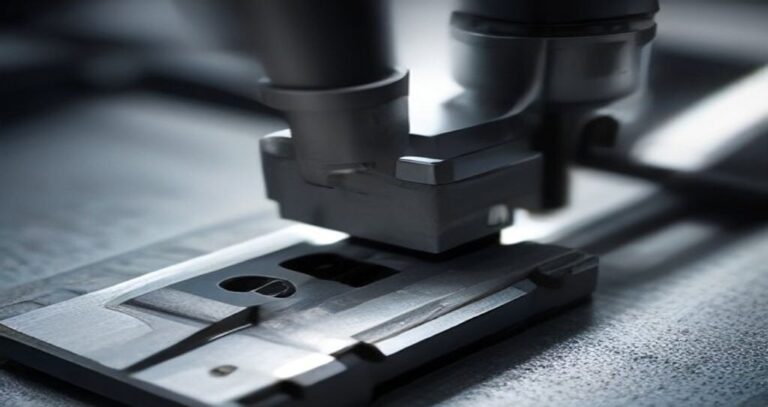
Choosing CNC Metal Cutting Machines is usually framed as a spec-sheet comparison: spindle speed, axis count, bed size, price. That framing misses the point. What actually determines whether a job runs profitably is whether the machine matches the parts you make, the tolerances you quote, and the materials you cut. Buy a machine for the brochure and you can spend years working around its limits. Buy it for the work, and the rest follows.
This guide is written for engineers, sourcing managers, and product development teams who have to justify a capital purchase and live with the result. We look at seven practical machine and setup choices, and we map each one to real outcomes: achievable tolerances, suitable materials, cycle time behavior, and how the choice shows up in part cost. No hype, just the tradeoffs a shop actually feels.
Here is what we cover:
- How CNC Metal Cutting Machines differ in stiffness, thermal behavior, and damping, and why that matters more than peak spindle rpm.
- Three-axis versus four- and five-axis setups, and when the extra axes pay for themselves in reduced fixturing and fewer operations.
- Turning centers, mill-turn platforms, and when one machine replaces two.
- Tooling, workholding, and coolant decisions that quietly set your floor on tolerance and surface finish.
- How to read a quote or a capability sheet and connect it back to the parts in your own backlog.
The goal is straightforward. By the end, you should be able to look at a part print and a volume forecast and say which of these CNC Metal Cutting Machines fits, what it will hold, and roughly what it will cost per part. That is a more useful answer than a spec sheet alone gives you.
What CNC Metal Cutting Machines Actually Do
Strip away the enclosures and control pendants, and every one of these machines does the same job: it moves a sharp edge through metal along a controlled path while managing the heat and force that come with the cut. The differences live in how the axes move, how fast the spindle turns, and how stiff the whole structure is under load. Those three variables decide whether a part comes off the table on size or needs rework.
Milling platforms spin a tool and move it in multiple axes. A three-axis mill handles X, Y, and Z, which covers plenty of prismatic work: brackets, plates, housings with features on one face. Add rotary axes and you get 4-axis and 5-axis CNC Metal Cutting Machines that can reach compound angles and contoured surfaces in a single setup. That matters for parts where repositioning would stack tolerance errors.
Turning machines do the opposite. The workpiece rotates and a stationary tool removes material, which makes them the natural choice for shafts, bushings, fittings, and anything with rotational symmetry. Live tooling on a turn-mill lets the same platform drill and mill off-axis features, so a shop can finish a part without a second operation. Many production floors run turning centers and machining centers side by side for exactly this reason.
Multi-axis and mill-turn platforms blur the line. A five-axis machining center with a trunnion table, or a turn-mill with a B-axis head, can approach a feature from nearly any direction. Setup count drops, and so does the risk of fixture-induced error. The tradeoff is programming time and the cost of verifying that the post-processor produces what the CAM system promised.
Spindle speed sets the ceiling on cutting speed. In aluminum, high spindle speeds let small-diameter tools run at the surface footage the material wants, which keeps chip evacuation clean and cycle times short. In titanium and hardened steels, the same spindle is usually run far slower because heat concentrates at the edge. Speed alone does not solve anything if the tool cannot survive the temperature.
Rigidity decides what the machine can hold. A stiff frame, preloaded linear guides, and a rigid spindle resist deflection when the cutter bites. Push a light machine too hard in steel and the walls chatter, the finish goes, and the tolerance drifts. Heavier CNC Metal Cutting Machines with box ways or large linear guides tend to hold size better in tough alloys, at the cost of speed on lighter work.
Control resolution and servo tuning shape accuracy at the detail level. Encoder feedback, backlash compensation, and look-ahead in the control determine how faithfully the machine follows the programmed path, especially through small radii and tight corners. A machine rated at fine resolution still cuts poorly if the servos cannot keep up with the feed rate.
Put those factors together and the tradeoffs for aluminum, steel, and titanium start to make sense. Aluminum rewards spindle speed and fast rapids. Steel wants rigidity and thermal stability. Titanium demands both stiffness and enough torque to keep the cutter engaged without rubbing. No single configuration wins everywhere, which is why shops match CNC Metal Cutting Machines to the material mix and part family they run most. When selecting CNC Metal Cutting Machines, confirm the spindle taper matches your planned tooling sizes and torque needs. In-process probing on CNC Metal Cutting Machines catches drift early and reduces scrapped parts on critical features.
Quoting should include cycle time estimates derived from the actual capabilities of your CNC Metal Cutting Machines.
CNC Metal Cutting Machines Compared By Type
Vertical machining centers are the default starting point for most shops. The spindle points down, the table moves in X and Y, and the operator has clear sight of the cut. Setup is straightforward, workholding is flexible, and a 3-axis vertical mill can typically hold ±0.001 in. to ±0.005 in. on production parts, depending on machine condition and fixturing. This class of CNC Metal Cutting Machines handles plates, housings, brackets, and most prismatic work without drama.
Horizontal machining centers flip that geometry. The spindle sits horizontal and the part mounts on a tombstone, so chips fall away instead of nesting in the pocket. That matters in deep bores and long pockets where chip evacuation drives tool life. Horizontals often carry pallet changers, which keeps the spindle cutting while an operator loads the next part. Tolerance capability is similar to a good vertical, but the real gain is throughput on cube-shaped parts run in volume.
Turning centers with live tooling blur the line between lathe and mill. The main spindle turns the part; a driven tool station mills flats, drills cross holes, and taps off-axis features without a second op. For shafts, fittings, and turned parts with a few milled details, this configuration removes a whole setup. Typical turning tolerances land around ±0.0005 in. to ±0.002 in. on diameter when the machine is well maintained.
Five-axis machining centers add two rotary axes, either as a trunnion table or a spindle head. The payoff is access to compound angles in a single setup and the ability to keep a short, rigid tool engaged on contoured surfaces. Blisks, impellers, medical implants, and complex aerospace brackets are the classic fits. Positioning accuracy on a well-maintained 5-axis machine is often in the ±0.0002 in. to ±0.001 in. range, though thermal drift and rotary calibration decide what you actually hold across a shift.
EDM covers what milling cannot. Wire EDM cuts hardened steels and tight internal corners with kerfs measured in thousandths, and sinker EDM burns cavities into materials that are impractical to mill after heat treat. Neither process cares much about material hardness, which is why tool and die shops lean on them. They are slower than milling, so they earn their place on features where geometry or hardness rules out a cutter.
Not every angled feature justifies a 5-axis purchase or a 5-axis slot on the schedule. A 3-axis mill plus a well-made fixture, an angle plate, or a tilting vise can often hit the same tolerance at a fraction of the hourly rate. The deciding question is straightforward: does the part need simultaneous motion to reach the geometry, or just a different orientation? If a fixture can present the face square to the spindle, run it on the 3-axis. Save the 5-axis for true contoured surfaces and parts where repositioning would stack error.
Each of these CNC Metal Cutting Machines brings a distinct strength, and most shops run several types side by side rather than betting on one. The comparison below sketches where each fits.
| Machine type | Typical tolerance | Best-fit geometry |
|---|---|---|
| 3-axis vertical mill | ±0.001 to ±0.005 in. | Plates, housings, prismatic parts |
| Horizontal mill | ±0.001 to ±0.003 in. | Cube parts, deep pockets, high volume |
| Lathe with live tooling | ±0.0005 to ±0.002 in. | Shafts, fittings, turned-plus-milled parts |
| 5-axis machining center | ±0.0002 to ±0.001 in. | Contoured, compound-angle, single-setup parts |
| Wire and sinker EDM | Sub-thousandth on many features | Hardened steel, sharp internal corners, cavities |
Matching the machine to the part family keeps cost and lead time in check. When a job needs several of these processes under one roof, working with a partner that runs both milling and turning can simplify sourcing. GreatLight provides Custom CNC Machining Services across prototypes and production, with inspection built into the process. Choosing among CNC Metal Cutting Machines comes down to geometry, tolerance, and volume, not brand loyalty. For small-batch fixture work, CNC Metal Cutting Machines with quick-change pallet systems reduce idle spindle time between jobs. Operators need training on offsets and wear compensation before CNC Metal Cutting Machines hold close tolerances reliably.
Regular ballbar testing keeps CNC Metal Cutting Machines within the circularity tolerances your customers expect.
Matching Materials To Cutting Machines
Material properties decide more about your process than the machine brochure does. Hardness, thermal conductivity, work-hardening tendency, and chip behavior all push tooling, coolant, and feed rates in different directions. The same CNC Metal Cutting Machines that hog aluminum at 10,000 rpm may struggle to hold tolerance in Inconel without a completely different setup.
Aluminum is the easy one, and that is why it is a poor benchmark for anything else. It cuts fast, conducts heat away from the edge, and forms soft, gummy chips that evacuate well with high-pressure coolant or even air blast. Two-flute and three-flute carbide end mills with polished flutes run at high surface speeds, often in the range of 1,000 to 2,000 SFM in production. Watch for built-up edge on softer tempers; sharp geometry and generous rake angles solve most of it.
Stainless steels sit in the middle and punish lazy parameters. Austenitic grades like 304 and 316 work-harden quickly, so a light pass with a dull tool hardens the surface and ruins the next cut. Keep chipload high enough to stay under the hardened layer, use rigid setups, and choose coatings that resist the heat that stays in the cut rather than escaping into the chip. 17-4 PH in its aged condition behaves closer to a tool steel than a 300-series stainless.
Tool steels and hardened alloys shift the conversation toward hardness. Annealed D2 or A2 mills like a tough alloy steel, but once you push past roughly 45 HRC, conventional carbide cutting gets expensive fast. This is where hard milling earns its place: coated carbide or CBN tools, light radial engagement, high spindle speed, and minimal coolant or none at all. Above roughly 55 to 60 HRC, many shops move to EDM for finishing, since the cutting forces and tool wear on CNC Metal Cutting Machines stop making economic sense.
Titanium and nickel alloys are the thermal problem children. They hold heat at the cutting edge instead of letting it leave with the chip, so tool life drops sharply if you push surface speed. Titanium 6Al-4V is often run at roughly 150 to 300 SFM with carbide, copious high-pressure coolant, and sharp edges that minimize rubbing. Nickel superalloys like Inconel 718 are worse; they work-harden, resist deformation, and demand rigid tooling, conservative feeds, and often ceramic or advanced coated inserts for roughing.
| Material | Relative Machinability | Coolant Strategy | Typical Tooling |
|---|---|---|---|
| Aluminum | Excellent | Mist, air, or flood | Polished carbide, high helix |
| Stainless (304/316) | Moderate | Flood, high pressure | Coated carbide, sharp edge |
| Tool steel (hardened) | Poor above 45 HRC | Air blast or dry | Coated carbide, CBN |
| Titanium 6Al-4V | Poor | High-pressure flood | Sharp carbide, low speed |
| Nickel alloys | Very poor | High-pressure flood | Ceramic, coated carbide |
Feed rates follow the same logic. Soft, conductive materials tolerate aggressive chiploads because heat exits with the chip. Titanium and nickel alloys force you to trade speed for tool life, which is why many shops apply trochoidal toolpaths and dynamic milling to control radial engagement rather than slowing the whole program. The Numerical control side of the equation matters here too: look-ahead, feed override, and adaptive clearing strategies on modern CNC Metal Cutting Machines let operators hold that balance without babysitting every pass.
Knowing when to stop cutting is just as important as knowing how. Hard milling and EDM are not fallbacks for weak shops; they are deliberate choices for materials where conventional turning and milling burn through tools and time. Matching material to method, then to the right CNC Metal Cutting Machines, keeps cost per part predictable instead of a daily gamble. Programmers should verify that CNC Metal Cutting Machines support the specific G-code dialects their CAM software posts. Coolant selection affects surface finish and tool life on CNC Metal Cutting Machines, especially in deep-pocket milling.
A preventive maintenance schedule for CNC Metal Cutting Machines protects spindle bearings and ballscrew accuracy over years.
Tolerances And Surface Finish Realities
The tolerance on a drawing is a request. What the shop can actually hold depends on how many setups the part needs, how rigid the fixture is, how much the spindle and workpiece move as they heat up, and how the feature gets measured at the end. Two shops running comparable CNC Metal Cutting Machines can quote the same part and land on very different results for exactly these reasons.
Setup count is the first multiplier. Every re-fixturing adds a new datum stack, and the errors accumulate. A part machined in one operation on a 5-axis machine has far fewer places for stack-up to creep in than the same part run across three vises on three separate machines. When a print calls for position tolerances under roughly ±0.025 mm, the process plan matters more than the machine’s published accuracy spec.
Fixturing decides whether the machine can even express its capability. Thin walls deflect under clamping pressure, long parts sag between supports, and soft jaws that look solid can shift a few microns under interrupted cuts. Shops that hold tight tolerances usually spend real engineering time on workholding before the first chip. That investment is invisible on a quote sheet, but it shows up in the acceptance report.
Thermal drift is the quiet one. A spindle running for hours grows; chips pile up and change the thermal picture; a shop door opening on a cold morning moves the whole frame. For work in the ±0.01 mm range, many shops run warm-up cycles, keep a climate-controlled cell, and schedule the tightest features early rather than at the end of a long run. None of that is exotic. It is just discipline applied to CNC Metal Cutting Machines that are otherwise capable enough.
Inspection closes the loop. A tolerance you cannot measure is a tolerance you cannot claim. Calipers and micrometers are fine for general work, but tight features often need a CMM, a height gauge on a surface plate, or an optical comparator, all run in a temperature-stable room. If the inspection method has more uncertainty than the tolerance itself, the number on the report is meaningless.
| Work type | Typical achievable tolerance | Typical surface finish (Ra) |
|---|---|---|
| General machining | ±0.1 mm | 3.2 µm |
| Precision machining | ±0.025 mm | 1.6 µm |
| Tight-tolerance work | ±0.005 to ±0.01 mm | 0.4 to 0.8 µm |
Those ranges are not hard walls. They are the bands where most shops stay comfortable without heroics. Moving from the top row to the bottom row is not a small step. It changes the machine, the fixturing, the inspection plan, the cycle time, and how many parts get scrapped before the process stabilizes.
That is the cost step worth understanding in detail. A ±0.1 mm bracket and a ±0.01 mm hydraulic manifold might use similar CNC Metal Cutting Machines, but the second one carries extra setup time, slower feeds to control finish, in-process checks, and a higher scrap allowance. Prototype runs feel this hardest. When a design calls for cosmetic surfaces on formed and machined parts, the finishing sequence deserves its own review, and this breakdown of CNC Prototype Sheet Metal Parts Surface Treatment Explanati is a useful reference for planning that step.
Surface finish follows a similar logic. Ra values improve with higher spindle speeds, sharper tooling, smaller stepovers, and rigid setups, but each of those trades against cycle time. A 0.8 µm finish on a sealing face is routine. Chasing 0.4 µm across a large contoured surface can double the run time, and it may still fail if the fixture lets the part ring.
The practical takeaway: write the tolerance the function needs, not the tightest number the CAD system will display. Then ask the shop how many setups it takes, how the feature will be checked, and what happens to price if the tolerance loosens one grade. Suppliers who run capable CNC Metal Cutting Machines will answer those questions directly, because they already know where their process is stable and where it is not. Rigid tapping on CNC Metal Cutting Machines depends on synchronized feed and spindle control, so test it during runoff. Lead time for new CNC Metal Cutting Machines often depends on spindle options, controller choice, and delivery scheduling.
When floor space is limited, compact CNC Metal Cutting Machines can still deliver the rigidity needed for steel parts.
Setup, Fixturing, And Workholding Decisions
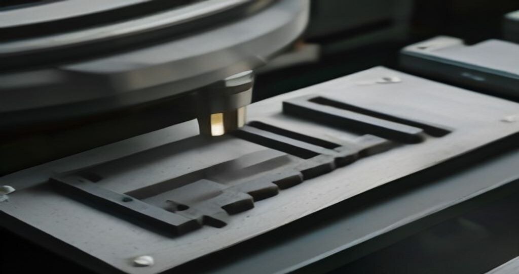
Toolpaths get the attention, but the fixture decides whether a process repeats. A weak workholding setup shows up as chatter, inconsistent dimensions, and cycle times that creep upward as operators compensate. Even the best CNC Metal Cutting Machines in a shop will still produce scrap if the part moves between passes.
Start with the simplest option that holds tolerance. Plain machine vises work well for prismatic parts with parallel faces and modest accuracy demands. Move to soft jaws when you need to grip a finished surface, hold an odd profile, or control concentricity. Soft jaws bored in place on the machine match the actual spindle and jaw position, which is why they typically hold location better than a generic set of hardened jaws.
For higher volumes, dedicated fixtures pay for themselves quickly. A tombstone turns a single-spindle mill into a multi-part producer by presenting several faces to the tool in one cycle. The trade-off is setup time and floor space. Tombstones make sense when the part runs for weeks or months and the load-unload motion stays outside the cut.
Thin plates and parts with no safe clamping surface push shops toward vacuum plates. Vacuum workholding distributes force across a large area, so it resists distortion on aluminum and other non-ferrous stock. It gives up grip on small footprints and needs a clean, flat sealing surface. Zero-point systems solve a different problem: they cut the time to swap a fixture from one job to the next. A receiver plate stays on the table, and pre-loaded pallets drop in and lock with repeatability often measured in the low thousandths.
That repeatability is what lets a shop move a job off one of its CNC Metal Cutting Machines and back on without re-indicating every time.
Match the fixture strategy to the volume, not to habit:
- Prototypes and one-offs: standard vise or soft jaws, minimal dedicated hardware, fast teardown.
- Low-volume repeat jobs: modular fixturing or a simple plate with dowel pins for location.
- Mid to high volume: dedicated fixtures, tombstones, or multi-part nests to shorten cycle time per part.
- Mixed high-mix work: zero-point receivers so changeover happens off the machine.
Fixture design also sets the datum scheme. Pick locating features that exist in the CAD model and survive downstream operations. If the fixture references a surface that gets machined away later, every following setup inherits that error. Good fixturing keeps the same three-point location and clamp direction across operations, which reduces stack-up and makes inspection results easier to trust.
Clamping force deserves a number, not a guess. Too little and the part lifts or spins; too much and thin walls bow, then spring back after unclamping. In many shops, the fix is to clamp over a supported section and keep the clamp directly above the locator. That way the cutting force travels into the fixture instead of tipping the part.
Cycle time ties directly to how fast an operator can load and unload. A fixture that takes two minutes to set up eats the savings from a faster toolpath. That is why shops running productive CNC Metal Cutting Machines invest in pallet changers, quick-change jaws, and standardized receiver plates. Setup reduction is often the largest available gain on a mature process.
None of this works without inspection feedback. Measure the first part, measure a part after a few hours of run time, and confirm the fixture still holds. Thermal growth, chip packing, and clamp wear all move the part over a shift. A fixture that holds tolerance at 8 a.m. may not hold it at 4 p.m. on a machine that has been cutting all day.
When you evaluate a supplier’s process, ask how they fixture the part and why they chose that method. Shops that run capable CNC Metal Cutting Machines can explain the trade-offs between a vise, a tombstone, and a zero-point system for your specific part. GreatLight builds fixtures around the job, from prototype soft jaws to production pallets, and inspects the result before it ships. Before quoting tight-tolerance parts, confirm the accuracy specifications of your CNC Metal Cutting Machines against the drawing. Spindle runout measurement should be part of incoming inspection for all new CNC Metal Cutting Machines.
Inspection And Quality Control Workflows
Inspection is not a step that happens after machining. It is planned while the quote is being built. When an engineer reviews a print for a set of CNC Metal Cutting Machines, they decide which features need in-process probing, which need a CMM, and which can be verified with hand tools. That decision shapes the process plan, the fixture design, and the tolerance stack before a single chip is cut.
In-process probing is usually the first line of defense. On a 5-axis mill, a spindle-mounted probe can touch off a bore or a face between operations and feed the offset back to the control. This catches thermal drift and tool wear before a feature runs out of tolerance. It also reduces the need to tear a part off the table for a bench check, which matters when the part is heavy or the setup is complex.
Probing does not replace a coordinate measuring machine. A CMM gives you a full dimensional report with traceable uncertainty, which is what most aerospace and medical customers expect. For tight-tolerance work, the sequence often looks like this:
- Probe critical features in-process to hold size during the run.
- Pull the part after the final op and let it stabilize to room temperature.
- Run a CMM program that reports every datum and tolerance zone.
- Log the results against the print and the job traveler.
Surface roughness is measured separately. A profilometer or a portable roughness tester gives Ra values that a CMM cannot. For sealing faces, bearing bores, and medical implant surfaces, that number is often called out on the print. Shops typically check it on a sample basis rather than every part, unless the customer specifies full inspection. On CNC Metal Cutting Machines with high-speed spindles, surface finish can shift with feed, speed, and tool wear, so the check is part of process control, not just final acceptance.
First-article inspection is the formal gate. The first part off a new setup gets a full dimensional layout, often with a ballooned print and a numbered report. This is where a shop proves the process, the fixture, and the program all agree with the customer’s drawing. For aerospace and medical work, the FAI package may also include material certs, heat treat records, and plating or coating documentation. Automotive customers often want a PPAP-style submission with capability studies on key characteristics.
Documentation ties it together. A CMM report without a revision level is worthless. Every inspection record needs to reference the correct drawing revision, the job number, and the date. When a customer audits the shop, they want to see that inspection planning started at quoting and that the results are traceable. That is also how a shop protects itself if a part is questioned later.
Not every job needs the same level of control. A prototype bracket may only need a few critical dimensions checked with calipers. A flight-critical housing on a set of CNC Metal Cutting Machines may need full CMM layout, surface finish checks, and a documented FAI before shipping. The skill is matching the inspection plan to the risk and the customer’s requirements, not over-inspecting every part until the job is unprofitable.
GreatLight runs inspection as part of the process, not as an afterthought, and ships parts with the documentation the customer’s quality system expects. If your next project needs Precision 5-axis work with a real inspection workflow behind it, send the print and the quality requirements. The shop will quote the machining and the inspection plan together, so there are no surprises when the first article lands on your desk. Aluminum jobs usually run faster on CNC Metal Cutting Machines with high spindle speeds and effective chip evacuation. High-mix shops benefit from CNC Metal Cutting Machines with large tool magazines to avoid frequent manual changes.

Industries Running These Machines Daily
Walk through any precision shop and you will see the same families of parts coming off CNC Metal Cutting Machines week after week. Aerospace brackets, medical housings, energy valve bodies, robot joints, automotive fixtures. Different alloys, different tolerances, but the same underlying question: can the process hold the print, batch after batch? That question drives how each industry specifies, validates, and audits its machining work.
Aerospace brackets are a good starting point because they punish everything. Typical materials include 7075 and 6061 aluminum, 15-5PH stainless, and titanium grades like Ti-6Al-4V. Titanium is where the trouble lives. It work-hardens fast, conducts heat poorly, and will destroy a cutter that dwells even briefly. Five-axis CNC Metal Cutting Machines handle the complex contours and thin walls these brackets often have, but the shop has to control tool engagement and coolant delivery tightly. Tolerances on hole positions and profile edges frequently sit in the plus or minus 0.001 inch range, with tighter callouts on mating surfaces.
Medical instrument housings bring a different constraint. The parts are often small, feature-dense, and made from 316L stainless, titanium, or sometimes PEEK and other polymers. Surface finish matters as much as dimension, since burrs or tool marks can trap contaminants. Process validation is heavy here. Shops working under ISO 13485 or similar quality systems document tool life, spindle speed, feed, and inspection results, then lock those parameters. Change a cutter vendor and the validation may need to be revisited. That is a real cost, and it is why medical work tends to stay with shops that already have the documentation discipline in place.
Energy valve bodies sit at the other end of the size range. These are often large, heavy, and machined from castings or forgings in carbon steel, duplex stainless, or Inconel. Wall thickness and bore concentricity drive the process. Many of these parts go into high-pressure service, so a dimensional miss is not just a scrap cost, it is a safety issue. Shops running CNC Metal Cutting Machines on valve bodies typically plan roughing and finishing as separate operations to let stress relieve between cuts.
Robotics joints and automotive fixtures round out the list. Robot joint housings need bearing bores held to tight roundness and perpendicularity, often in aluminum or cast iron. Fixtures for automotive lines are usually larger weldments or castings that get machined on multiple faces, and repeatability across a production run matters more than any single tight tolerance. See the basics of Milling (machining) for how these operations are categorized.
| Industry | Typical Material | Tolerance Focus | Validation Priority |
|---|---|---|---|
| Aerospace brackets | Aluminum, titanium, 15-5PH | Hole position, thin walls | High |
| Medical housings | 316L, titanium, polymers | Finish, small features | Very high |
| Energy valve bodies | Carbon steel, duplex, Inconel | Bore concentricity, wall thickness | High |
| Robot joints | Aluminum, cast iron | Bore roundness, perpendicularity | Moderate to high |
| Automotive fixtures | Steel weldments, castings | Repeatability across faces | Moderate |
Where does process validation matter most? Medical and aerospace, without much debate. Both expect documented first article inspection, traceable material certs, and a controlled process that does not drift. Energy runs close behind because of pressure boundary requirements. Automotive fixtures often tolerate looser individual tolerances but demand consistency across thousands of cycles.
The practical takeaway for sourcing teams is straightforward. Tell the shop what the part actually does, not just what the drawing says. A bracket that holds a sensor has different risk than one that holds a flight control surface. That context shapes how the shop sets up its CNC Metal Cutting Machines, how often it inspects, and how much margin it builds into the process. When buyers and machinists share that information early, the first article usually lands clean. When cutting stainless steel, CNC Metal Cutting Machines need sufficient torque at low rpm to avoid work hardening.
Program verification and dry runs on CNC Metal Cutting Machines prevent crashes that damage fixtures and tool holders.
Cost Drivers And Choosing A Machine Shop
Price per part is not one number. It is the sum of machine time, tooling wear, setup hours, inspection, and material yield. When a quote looks low, one of those five is usually being underestimated somewhere. Your job as a buyer is to find out which one, and whether that risk lands on you.
Machine time is the biggest lever on any CNC Metal Cutting Machines quote. A part that runs on a 3-axis mill in two setups at 12 minutes each costs far less spindle time than the same part in five setups. Cycle time also depends on how aggressively the shop can cut. Rigid setups and correct toolpaths let a machinist push feeds and speeds; a weak workholding setup forces conservative cuts. Ask what cycle time the quote assumes and whether it includes load and unload.
Tooling wear is where inexperienced buyers get surprised. Hardened alloys, abrasive composites, and interrupted cuts eat inserts fast. In many shops, tool cost on tough stainless or titanium work can run a meaningful fraction of the part price, not a rounding error. Shops quoting CNC Metal Cutting Machines for high-volume runs often track tool life per edge and budget replacements into the rate. A shop that does not track this is estimating, and estimates show up later as a price increase or a quality drift.
Setup hours get spread across the order quantity. That is why the same part costs more at quantity 10 than at quantity 500. A good quote breaks setup out separately, so you can see what a design change or a smaller batch really costs. If setup is buried in the piece price, you cannot tell whether you are paying for a fixture or for inefficiency.
Inspection is the fourth driver, and it scales with tolerance, not with part size. A bracket held to plus or minus 0.5 mm needs a caliper check. A medical or aerospace component with true position and surface finish callouts may need CMM time on every unit or on a sampling plan. That time is real and it belongs in the price. Cutting inspection to win a quote is rarely a good trade.
Material yield ties all of it together. Bar stock, plate, and near-net forgings all price differently, and the drop you pay for but never ship is pure cost. Ask what stock size the shop assumes and how much remnant is charged to the job.
Before awarding work, put these questions to the supplier:
- Which CNC Metal Cutting Machines would run my part, and how many axes?
- What is your current spindle capacity, and how does my lead time fit it?
- Do you cut this material regularly, and what tooling do you standardize on?
- Who programs the job, and can I review the setup sheet before the run?
- What inspection equipment covers my tightest callout, and what is the sampling plan?
- How do you handle a first article, and what happens if it fails?
- What is your process for a design revision mid-order?
Quality systems matter as much as iron. Ask whether the shop works to a documented process, how it calibrates instruments, and how it records nonconformances. Shops running modern CNC Metal Cutting Machines usually have the data. The question is how consistently they use it.
Finally, match the shop to the job. A prototype house with fast changeover and skilled setup people will often beat a high-volume shop on a 20-piece order, and lose badly on a 20,000-piece release. Selecting CNC Metal Cutting Machines and the shop behind them is a fit problem, not a spec-sheet contest. Compare two or three suppliers on the same questions, and the price differences stop looking random. Thermal growth in CNC Metal Cutting Machines can shift dimensions during long runs, so plan warm-up cycles and checks. Chip conveyors and filtration on CNC Metal Cutting Machines matter when cutting cast iron or abrasive materials.
Choosing CNC Metal Cutting Machines That Fit
Seven machine types, one decision: match the process to the part. Job shops often run a 3-axis mill for prismatic work, a lathe with live tooling for turned parts, and a 5-axis machine when features demand multi-face access. The right CNC Metal Cutting Machines reduce setups, hold tolerances, and keep cycle times predictable.
Before you buy or outsource, pin down four things:
- Material and hardness, since aluminum cuts differently than titanium or hardened tool steel.
- Tolerance and finish callouts, because tight limits change machine and fixturing choices.
- Part size and geometry, which dictate work envelope and axis count.
- Volume, from one-off prototypes to repeat production runs.
Cost drivers follow the same logic. Machine hour rates, setup time, tooling wear, inspection effort, and material scrap all move the quote. A shop running the wrong CNC Metal Cutting Machines for your part may pad the price to cover risk. A shop running the right ones can quote tighter and hold the print.
If you are still comparing options, send drawings early. A machining partner can flag features that drive cost, suggest tolerance relaxations that do not affect function, and recommend a process before metal is cut. GreatLight handles prototypes through production with 5-axis milling, turning, and documented quality inspection, so you get parts that match the drawing.
Request a quote on your next project. Include material, quantities, critical tolerances, and finish requirements. That gives any supplier enough to price the work accurately and confirm their CNC Metal Cutting Machines can deliver it. Fixture design should account for the travel envelope and table load limits of your CNC Metal Cutting Machines. For titanium components, CNC Metal Cutting Machines require rigid structures and generous coolant pressure at the cut.