
CNC Machining of Mill-Turn Parts
One machine, one chucking: turning and milling in the same cycle. This page explains how mill-turn removes setup error, when the method pays off, and where it still loses to separate lathe and mill work.
In this article
- 1
- 2
- 3
- 4
- 5
- 6
What makes CNC machining of mill-turn parts different
In CNC machining of mill-turn parts, a single machine holds the blank in a spindle or chuck that rotates like a lathe, while a second spindle carries a live tool that spins like a mill. The part can be turned to a diameter, then have flats, slots, holes, or helical ports cut into it without ever leaving the workholding. That is the whole point. Every time a part moves between machines, the datum shifts, even by a few microns.
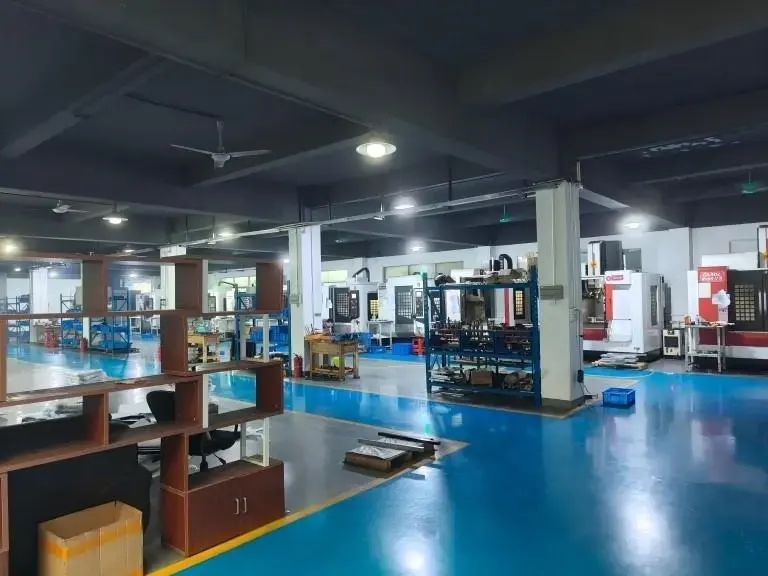
A standard lathe with live tooling can drill and tap on centerline or on a face, and that covers a lot of work. A true mill-turn center adds a B-axis tool head and often a Y-axis, so the tool can approach at an angle and mill off-center pockets, keyways, and angled faces in the same cycle. We run 16 mill-turn centers alongside 16 simultaneous 5-axis machining centers, and the split between them comes down to part shape, not machine prestige.
The distinction matters for your drawing review. If a part is mostly a body of revolution with a few cross features, mill-turn is the natural process. If the part is a prismatic block with one bored hole, a 3-axis or 4-axis mill is faster and cheaper. Mill-turn wins when the part has a rotational axis and the cross features are dimensioned to the turned surfaces, because those relationships survive when there is no re-clamping.
One more boundary: mill-turn is not a synonym for 5-axis. A mill-turn center with B-axis and subspindle can finish six faces of a part, but a trunnion 5-axis mill can reach into deep cavities on a block that never rotates as a turned diameter. Know which axis you actually need before you ask for either.
Why one setup holds concentricity and position
The core error source in turned-and-milled parts is the second setup. The operator dials in a bore and clamps on a turned diameter, and the stack of chuck runout, soft jaw wear, and chip trapped under a jaw shows up as an eccentricity that no machine accuracy can remove. A 0.010 mm jaw error becomes 0.010 mm of position error on the cross hole. Mill-turn deletes that step, so the error budget only contains spindle and slide accuracy.
On the machines in our shop, work that used to run as two operations can hold ±0.005 mm on the relationship between a turned OD and an off-axis hole. That is not a machine spec claim in isolation. It is what the elimination of a re-fixture buys you. The turned diameter and the milled pocket are cut in the same coordinate frame, measured in the same cycle.
Thermal behavior changes too. The part stays clamped once, so it does not cool between operations and then get clamped back into a distorted shape. Thin-wall bodies, which move when you release a chuck, keep their roundness because the turning and the milling happen while the part is still supported the same way.
The trade-off is programming and tooling cost. A mill-turn program is more involved than a lathe program plus a mill program run separately, and live toolholders with Y-axis capability are expensive. For a two-piece prototype that is hard to justify. For a 500-piece family of valve bodies, the setup removal pays for itself quickly.
Toolpaths, spindles, and bar work in practice
A mill-turn cycle usually starts with OD roughing and finishing while the main spindle rotates, then switches to live tooling for cross features. If the machine has a subspindle, a bar feeder can push stock through the main spindle, part it off, and hand the part to the subspindle for back-end work. That is how a fitting with threads on both ends comes off complete with no manual handling.
Cutting parameters follow the operation, not the machine. Turning aluminum 6061 runs at high surface speed with generous feed; live milling on the same part uses smaller radial engagement because the tool is held in a turret or a B-axis head with less stiffness than a dedicated mill spindle. Feed rates for live tools typically sit 20 to 40 percent below what the same cutter would run in a 40-taper mill. Pushing harder causes chatter that shows on the finished diameter.
Bar capacity sets the upper limit for unattended work. Parts that fit within the bar diameter and the machine's Z travel can run lights-out. Parts that must be chucked individually still benefit from one setup, but they need an operator to load each blank. We machine up to 4,000 mm in our larger platforms, though mill-turn bar work is normally in the smaller diameter range.
For long parts, a subspindle or tailstock supports the free end. Without it, a slender turned section deflects under cutting force and the diameter goes tapered. If your part has a long unsupported length, say a 12 mm diameter over 150 mm, expect to add a steady rest or accept a slower cycle with light passes.
Material behavior on a mill-turn center
Aluminum is the easy case. Grades like 6061-T6, 6082, and 7075 turn and mill well with sharp tooling and good chip evacuation. The risk is built-up edge on the live tools when coolant is marginal, which leaves a torn finish on a milled face. High-pressure coolant through the tool solves most of it.
Stainless steels such as 303, 304, and 316 work well for turned features but work-harden under live milling if the cutter dwells. 17-4PH in the H900 condition machines cleanly and is common in valve and pump parts. Keep the live tool moving, use a positive rake, and do not let a finishing pass rub.
Titanium TC4 (Ti-6Al-4V) and Inconel are where mill-turn earns its keep on complex parts, because each re-fixture on these alloys risks both scrap and tool wear. They also punish any lack of rigidity. On our platforms, titanium parts are cut at low surface speed with copious coolant and short tool life is planned into the cycle, not treated as a surprise.
Plastics like POM, PEEK, and PA turn easily but deflect under chuck pressure. Soft jaws or a collet with a controlled bore keep the part round. PEEK is abrasive and needs sharp, polished tooling. For all of these, the mill-turn advantage is the same: fewer chances for the part to move between operations.
How to design a part that suits mill-turn
Start with a dominant axis. If 70 percent or more of the material removal happens around one centerline, mill-turn is a strong candidate. The remaining cross features should be reachable from the turret or B-axis head without the tool shank colliding with the chuck. Deep radial holes, for example a cross hole with a depth more than four times its diameter, need a long, thin tool that will chatter. Plan those as a separate operation or redesign the depth.
Dimension your critical relationships from the turned datum. This is the design move that converts mill-turn into a real accuracy gain. If a bolt circle is called out from the OD, one setup holds it. If the drawing calls it out from a milled face that itself comes from a second setup, you have reintroduced the error you were trying to avoid.
Keep wall sections reasonable. A mill-turn center grips the part harder than a mill vise, and a 1 mm wall on a Ø80 mm aluminum body will ovalize under chuck pressure even with soft jaws. Thicker walls, or a design that lets the part be supported on a solid section during turning, hold form far better.
Finally, consider the back side. If the part needs a faced and threaded rear end, specify whether a subspindle can reach it. Designing the second end to be simple lets the machine finish it in the same cycle. If the rear end has complex features, one setup may not cover it, and you are back to a two-operation route.
Mill-turn vs. separate turning and milling
Use this to decide which route fits the part in front of you.
| Factor | Mill-turn center | Separate lathe + mill |
|---|---|---|
| Part shape | Body of revolution with cross features | Prismatic block or simple turned part |
| Typical run size | Prototype through 10,000+ parts | Any size, easiest for one-offs |
| Concentricity / position | Held in one setup, ±0.005 mm | Depends on second-setup dial-in |
| Setup time | One setup, longer program | Two setups, two programs |
| Live tool rigidity | Lower than a mill spindle | Full mill spindle stiffness |
| Deep radial features | Limited by turret reach | Easier with a dedicated mill |
| Cost driver | Programming and live tooling | Labor and fixture time |
| Best fit | Valve bodies, fittings, hubs, shafts | Brackets, plates, housings, simple pins |
The short answer
If the part spins around one axis and its critical cross features are dimensioned from turned surfaces, run it as a mill-turn part. If it is a block with one hole, or the cross features are deeper than four times their diameter, split the work across a lathe and a mill.
Questions engineers ask about mill-turn
Is mill-turn the same as 5-axis machining?
No. A mill-turn center turns the part and mills with live tooling, usually with a B-axis head and sometimes a Y-axis. A 5-axis mill moves the tool or the part on two rotary axes to reach angled faces on a prismatic part.
Some mill-turn centers can position on five axes, but the workholding and the intended part family are different. We quote both routes when a part could go either way.
What tolerance can mill-turn actually hold?
On our platforms, mill-turn work holds ±0.005 mm (±0.0002 in) on features cut in the same setup. That applies to the relationship between a turned diameter and a milled cross feature.
If a feature needs a second setup, the achievable tolerance depends on the fixturing, not the machine. We tell you which features fall into which group before quoting.
How deep can a cross hole be before mill-turn stops making sense?
A practical limit is a depth-to-diameter ratio of about 4:1 for a live tool held in a turret or B-axis head. Beyond that, tool deflection and chatter degrade the hole and shorten tool life.
Deeper cross holes are better cut on a mill where the tool is held in a stiff spindle. We often split the part into a mill-turn front end and a milled back end for this reason.
Can mill-turn handle bar-fed, lights-out production?
Yes, when the part fits the bar diameter and the machine's Z travel. The subspindle picks up the parted-off part and finishes the back end without an operator.
Parts that need individual chucking still get the one-setup benefit, but they need an operator to load each blank. We will tell you which category your part is in during DFM review.
Does mill-turn work for titanium and Inconel?
It is often the better choice for these alloys on complex parts, because fewer setups means fewer chances to scrap an expensive near-net blank.
The trade-off is speed. Titanium TC4 (Ti-6Al-4V) and Inconel run at low surface speed with heavy coolant, so cycle time is longer than the same geometry in aluminum.
What do you need to quote a mill-turn part?
A 3D model and a 2D drawing with datums, tolerances, material, and finish. Tell us which features are critical and how the part is inspected.
We return a quotation and a free DFM analysis within 12 hours, and there is no minimum order quantity, from one prototype to 10,000+ part runs.
Send us the part and we will tell you if it should be mill-turn
Upload a model and drawing. You get a quotation and a free DFM analysis within 12 hours, with a clear answer on which process fits.
12-hour quote±0.005 mm100% inspectionNo minimum order quantity
More machining notes
We publish setup notes, tooling trials and inspection data from the factory floor.











