
CNC Machining of Cavity Shell: How Hollow Parts Hold Their Shape
A cavity shell is a hollow body with thin walls, deep pockets and often a sealing face. This page explains how CNC machining of cavity shell parts actually works: stock removal order, wall thickness limits, why bores drift, and where the process stops being the right answer. Written for design and process engineers who need to judge a drawing before it goes to a shop.
In this article
- 1
- 2
- 3
- 4
- 5
- 6
- 7
- 8
- 9
- 10
- 11
Key takeaways
What a cavity shell is, and why it is machined rather than cast
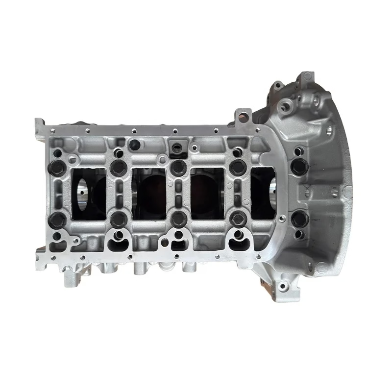
A cavity shell is a hollow enclosure: a pump housing, a gearbox cover, a valve body, a sensor can, a battery tray wall, or a mold cavity insert. It has an outer profile, an internal void, and usually at least one machined face that seals or locates against something else. The wall between the outer profile and the internal void is the defining feature. Everything difficult about the part comes from that wall.
Casting and forging give you the hollow shape cheaply, but they leave draft angles, parting lines and a skin that varies in hardness. When a bore needs to sit within ±0.02 mm of a mounting face, or a sealing groove needs Ra 1.6 μm, casting alone will not hold it. So the shell is cast or forged oversize, then CNC machining of cavity shell features brings the critical faces, bores and grooves into tolerance.
The reverse case also exists. A shell can be cut from solid plate when quantities are low, when the material is not castable to the required soundness, or when the internal geometry has features a mold cannot pull. Cutting from solid costs more per part in cycle time but removes tooling cost and porosity risk. For one-off and prototype cavity shells, solid stock is usually the faster route to a functional part.
Either way, the machining plan is the same in principle: establish a stable datum, remove the bulk of the material while leaving enough stiffness to survive the remaining cuts, then finish the surfaces that matter. The order matters more than the speeds and feeds.
- 1Machined shellCritical bores, seal faces and grooves produced after casting or from solid.
- 2Typical materials6061-T6, 7075, 304/316L, 17-4PH, 4140, plus POM and PEEK for non-metallic shells.
- 3Typical size rangeFrom a 30 mm sensor can to a 4,000 mm frame section.
Why thin walls move: cutting force, residual stress and heat
Three things push a thin wall out of position. The first is cutting force. A side mill pushes the wall away from the tool, then the wall springs back after the tooth passes. You get a wall that measures correct at the top and thin at the bottom, or a bore that is round in the fixture and oval on the bench. The lighter the radial depth of cut, the smaller this effect, which is why finishing a 1 mm wall with a 0.2 mm radial step and a sharp, high-rake tool is normal practice.
The second is residual stress. Rolled plate and extruded bar carry internal stress from the mill. Remove 70 percent of the material from one side and the balance tips; the part bows. Roughing leaves a defined allowance, then a stress-relief or natural aging step, then finishing. For a 300 mm aluminum shell with 3 mm walls, skipping that middle step is the most common cause of a bowed sealing face.
The third is heat. Aluminum conducts heat away quickly, so it grows during heavy cutting and shrinks back when it cools. The shrink is not uniform across a shell with thick flanges and thin panels, so a bore cut hot can finish undersize. Titanium and stainless keep heat at the edge instead, which shortens tool life and pushes the tool into the wall. Both effects shrink when the finishing pass is light and the coolant reaches the cut.
You cannot remove all three effects. You can keep them below your tolerance band by controlling the allowance left for finishing, the stiffness of the setup, and the temperature at which the final measurement is taken.
How many setups a cavity shell really needs
Count the directions from which a tool must reach the part. A simple open box needs one face for the cavity and one for the base. A housing with a bore on the end face, a sealing groove on the top, and mounting holes on two sides needs four directions at minimum. Each direction is either a separate operation with a re-clamp, or a rotary axis that indexes the part without letting go.
Every re-clamp adds a small positional error. If the drawing ties two features to each other within ±0.02 mm and they sit on opposite faces, a 4-axis or 5-axis setup that keeps one datum is the safer plan. A 4-axis mill with a Ø400 mm rotary table handles the common case of a shell with features around one axis. Simultaneous 5-axis handles contoured ports, angled seal faces and pockets that a three-axis tool cannot enter without a long reach.
Long reach is where accuracy quietly disappears. A tool that sticks out 6 times its diameter will deflect under load, and no amount of machine accuracy fixes that. When a cavity is deeper than about 4 times its smallest width, expect to either use a smaller tool with more passes, accept a looser tolerance on the floor and corner radii, or redesign the pocket with a larger corner radius so a stiffer tool can reach the bottom.
For very large shells, the practical limit is travel, not stiffness. With 4,000 × 400 × 150 mm of travel on the largest machines, a shell longer than 4,000 mm has to be split into sections or machined on a different platform.
- 1One setupOpen shells and shallow covers; best positional accuracy between features.
- 2Two to three setupsTypical housings; use a common datum and re-probe before the second op.
- 35-axis indexingPorts, angled faces and features on five sides without re-clamping.
- 4When to splitBeyond 4,000 mm, or when a deep internal feature needs its own access.
Sealing faces, bores and grooves: where the tolerance budget goes
A sealing face is a flatness problem, not a size problem. A cover that bolts down on an O-ring needs the face flat enough that the gasket compresses evenly. On a 200 mm aluminum flange, flatness within 0.05 mm is usually enough; the surface finish matters more, because a face machined to Ra 1.6–3.2 μm gives the gasket something to bite into, while a mirror-polished face can let it slip. We normally leave seal faces at Ra 1.6 μm unless the drawing asks for finer.
Bores are a size and roundness problem at the same time. A bearing bore at Ø40 H7 has to be round, straight and coaxial with the opposite bore. If the two bores are finished in one setup on a mill-turn or 5-axis machine, coaxiality is set by the machine, not by the operator. If they are finished in two setups, the second bore inherits the re-clamping error. For gearbox and pump shells, that single decision often decides whether the assembly runs quiet.
Grooves are the hardest small feature. An O-ring groove 2 mm wide and 1.5 mm deep in a 316L stainless shell needs a small-diameter tool with a short flute length, and the tool will deflect if the groove is far from a rigid wall. Groove width tolerance is usually tighter than groove depth tolerance, because width controls how much the O-ring squeezes. Cutting the groove before the surrounding face is finished is a common mistake; the finishing pass then throws a burr into the groove edge.
Threaded ports deserve a separate mention. A port on a curved or angled surface needs a spot face before drilling, or the thread starts crooked and the fitting leaks. Spot facing is cheap in the same setup and expensive as a rework.
Material choices and what each one does to the cavity wall
Aluminum is the default for cavity shells. 6061-T6 machines cleanly, holds a thin wall better than 7075 at the same thickness, and takes anodizing well. 7075 gives higher strength but is more prone to stress movement after heavy stock removal, so it suits thicker walls and parts where weight matters more than stability. Cast aluminum such as ADC12 machines fast but can hide porosity that shows up when a bore breaks into a void.
Stainless 304 and 316L resist corrosion and clean well, which is why pump and food-equipment shells use them. They work-harden, so a rubbing cut dulls the tool and pushes the wall. Sharp tools, consistent feed per tooth and no dwell in the cut. 17-4PH gives higher strength and can be aged after roughing, which is a useful way to finish a dimensionally stable shell.
Steel shells such as 4140 are usually for hydraulic and structural housings. They cut well in the annealed state and then get heat treated; plan for the distortion that heat treatment brings and leave grinding or hard milling allowance on the critical bores. Titanium TC4 and Inconel appear in aerospace and energy shells where temperature and weight rule. Both are slow, hot and expensive to cut, and thin walls in these materials need extra support.
Plastics behave differently again. POM and PEEK cut cleanly but move with temperature and moisture, so a shell measured the day it is machined may not match the drawing a week later. For plastic cavity shells, agree on the measurement condition before the first cut.
- 1Best thin-wall stability6061-T6 among aluminum grades; annealed 4140 among steels.
- 2Highest strength-to-weight7075 and Ti-6Al-4V, at the cost of more movement and cycle time.
- 3Corrosion and cleanability304, 316L and 17-4PH for pump, valve and medical shells.
- 4Dimensionally restlessPOM, PEEK and thin 7075; fix the measurement condition in writing.
Where CNC machining of cavity shell stops being the right process
CNC machining is a subtractive process with a fixed cost per cubic centimeter removed. As the hollow volume grows, that cost grows with it. A shell with a large internal void and modest tolerance needs is often cheaper as a casting or a weldment with machined interfaces. Machining makes sense where the critical features are few and the tolerance is tight, or where quantity is too low to justify tooling.
Deep, narrow cavities are the second boundary. A pocket 150 mm deep and 20 mm wide is a 7.5-to-1 depth-to-width ratio. A tool that reaches the bottom is thin, deflects, and leaves taper. You can machine it, but slowly, with a tapered tool or a smaller stepover, and the corner radius at the bottom will be small. If the design allows a larger corner radius or a two-piece shell, the part gets cheaper and more accurate.
Internal features that cannot be reached from any tool direction are the third boundary. An undercut inside a closed shell cannot be milled. Options are splitting the shell into two machined halves, using an insert or a plug, or changing to a process that forms the cavity around a core, such as casting or molding. Deciding this at the drawing stage saves a redesign later.
A final boundary is quantity. For runs above roughly 10,000 parts, the per-part economics of casting, forging or molding usually beat milling, even with the machining of critical faces added back in. Below that, and especially in the prototype and bridge-production range, CNC machining of cavity shell parts is usually the fastest route to a part that works.
Inspection: what to measure and when to measure it
A cavity shell fails in service for a small number of reasons: a bore out of round, a seal face not flat, a wall too thin at one point, or a port that leaks. Inspection should target those four, not just the outside profile. A CMM report on the outer shape tells you the machine was accurate; it does not tell you the bore will accept a bearing.
Measure wall thickness by ultrasonic gauge or by sectioning a first article, not by calipers at the open end. The thin point of a machined wall is usually at the bottom of a deep pocket where the tool deflected most, and that point is often out of reach of a caliper. First-article sectioning is the honest check, and it is worth doing once per design.
Measure bores and seal faces with the part free of the fixture. Clamping a thin shell round can hide an oval bore, and the part springs back after delivery. Temperature matters too: a 300 mm aluminum shell measured at 30 °C reads larger than the same part at 20 °C by about 0.07 mm. For tolerances below ±0.02 mm, agree on the measurement temperature.
For production runs, in-process probing catches drift before the part is finished. We inspect 100 percent of parts before shipment, with raw material checks, in-process monitoring and a final inspection, and reports are available on request.
Step by step: a workable machining sequence
This is the order we use for thin-wall cavity shells. It is a sequence, not a set of cutting parameters for every material.
- 11. Fix the datum before cuttingMachine a reference face and two reference edges first, or use a cast pad. Every later measurement comes back to this datum.
- 22. Rough with a defined allowanceLeave 0.3–0.5 mm per side on finish faces and open the cavity in layers. Do not thin the wall to final size yet.
- 33. Stress relieve or let it settleFor aluminum shells with walls under 3 mm, a stress-relief cycle or a settle period before finishing keeps the part from bowing.
- 44. Semi-finish and re-probeBring walls to 0.15–0.2 mm and re-check position. Correct the offset in the control rather than in the fixture.
- 55. Finish the sealing face and bores in one setupKeep the features that must agree with each other in the same clamping. Target Ra 1.6 μm on seal faces, finer only if specified.
- 66. Deburr, then measure unclampedRemove the part from the fixture before final measurement. In-fixture roundness reflects the clamp, not the part.
Wall thickness against achievable tolerance
Ranges below assume a supported setup, sharp tooling and a finishing allowance of 0.2–0.5 mm per side.
| Nominal wall | Practical tolerance | Main risk | Usual countermeasure |
|---|---|---|---|
| Above 5 mm | ±0.005 mm on bores | Low; deflection is minor | Standard 3-axis or 4-axis setup |
| 2–5 mm | ±0.01 to ±0.02 mm | Spring-back on deep walls | Light radial cuts, mid-support |
| 1–2 mm | ±0.02 to ±0.05 mm | Chatter and taper | 5-axis, short tools, wax or fixture support |
| 0.5–1 mm | ±0.05 mm and up | Wall collapse, heat growth | Rough, stress relieve, then finish |
| Below 0.5 mm | Not a milling target | Buckling under clamping | Consider sheet metal or chemical etching |
Which machining route fits which cavity shell
| Shell type | Best route | Why | Watch out for |
|---|---|---|---|
| Prototype housing, 1–20 pcs | 3-axis from solid plate | No tooling cost, fastest to first part | More cycle time per part |
| Housing with bores on two faces | 4-axis with rotary table | Coaxial bores finished in one setup | Rotary table capacity limit |
| Shell with angled ports | Simultaneous 5-axis | Tool reaches the port without re-clamp | Higher hourly rate |
| Thin-wall cover, 1 mm wall | Rough, stress relieve, finish | Removes residual stress before final cuts | Longer lead time |
| High-volume cast shell | Cast oversize, then finish | Low material cost per part | Porosity may appear at the bore |
| Very thin, large panel | Sheet metal fabrication | Milling cannot hold the wall | Different tolerance class |
The judgement call
If the shell has a few tight bores and seal faces and the walls are 2 mm or thicker, machine it from solid or from a casting and put the critical features in one setup. If the walls are under 1 mm, or the internal cavity is large and loose-tolerance with no machined features inside, change the design or the process: mill the interfaces and form the rest by casting, sheet metal or molding.
Questions engineers ask before releasing a cavity shell drawing
What is the minimum wall thickness you can machine reliably?
For aluminum and stainless, 0.5 mm is the practical floor on a supported part, and 1 mm is where tolerances stay reasonable, around ±0.05 mm. Below 0.5 mm the wall buckles under clamping and the finishing pass pushes it, so sheet metal or chemical etching is usually the better process.
The number depends more on wall height than on thickness. A 0.8 mm wall 10 mm tall behaves very differently from the same wall 80 mm tall.
How do I keep two coaxial bores aligned?
Finish both bores in the same setup. On a 4-axis machine with a rotary table, or on a 5-axis machine, the part stays clamped to one datum and the machine holds the relationship. If the bores must be finished in separate setups, re-probe the datum before the second op and expect a small additional error.
On a 200 mm gearbox shell, one-setup finishing typically holds coaxiality within 0.02 mm; two setups can drift to 0.05 mm or more depending on the fixture.
Why does my aluminum shell bow after machining?
Residual stress in the stock is released as material is removed. Rolled plate and extruded bar carry stress from the mill, and removing 70 percent from one side lets the part move. Roughing, then a stress-relief cycle or a settle period, then finishing is the standard fix.
For 7075 and for walls under 3 mm, allow for this in the schedule. Cutting the part to final size in one pass almost always produces a bowed sealing face.
How deep can a pocket be before accuracy drops?
Past about 4 times the tool diameter, deflection starts to matter; past 7 times, it dominates. A 20 mm wide pocket 150 mm deep is a 7.5-to-1 ratio and needs a tapered tool or a redesign.
If the drawing allows a larger bottom corner radius, a stiffer tool can reach the floor and the pocket gets both cheaper and more accurate.
Should the shell be cast first or cut from solid?
For prototypes and runs up to a few hundred parts, solid stock avoids tooling cost and porosity risk and gets to a functional part faster. For larger runs where the hollow volume is big and the tolerance on the outer shape is loose, casting oversize and finishing the critical faces is cheaper per part.
Either way, the machined features are produced the same way, so the tolerance on bores and seal faces does not depend on which route you take.
What surface finish should I specify on a sealing face?
Ra 1.6 μm is the usual target for an O-ring or gasket face; Ra 0.8–1.6 μm is achievable as a standard finish. Going finer than Ra 0.8 μm rarely helps a static seal and can let the gasket slip.
Specify the finish only where it matters. Calling out a fine finish across the whole shell adds cycle time for no functional gain.
Send the drawing, get a DFM read on the cavity
Upload your cavity shell model and drawing. We return a quotation and a free DFM analysis within 12 hours, flagging wall thickness, tool access and datum choices before the first cut. No minimum order quantity, from one prototype to 10,000+ part runs, and NDAs on request.
12-hour quote and DFM±0.005 mm tolerance100% inspection before shipmentNo minimum order quantity
More process notes from the shop floor
We publish setup notes, tooling trials and inspection data from the factory floor.











