
Anemometer Cup Rotor Machining: Geometry, Balance and Finish
Cup rotors are simple parts with unforgiving tolerances. This page covers what actually drives calibration drift: cup form, arm spacing, hub bore fit and mass balance. Written for instrument and mechanical engineers who need to specify a rotor that holds its calibration factor across a production run.
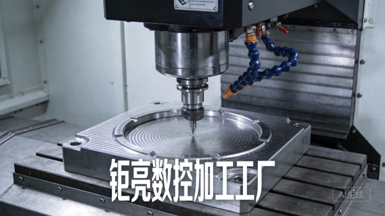
What Makes a Cup Rotor Hard to Machine
A cup rotor is three or four cups on radial arms around a hub. The difficulty is not the shape. It is holding the same shape on part 1 and part 500.
Why the Rotor Sets the Calibration Constant
Wind speed becomes rotation rate inside any cup anemometer. Drag on the concave face of each cup exceeds the drag on the convex back, so the rotor turns at a rate that is roughly linear with wind speed over the useful range. The calibration factor, the slope between rotation rate and wind speed, is determined by cup geometry and by the friction in the bearing below it.
This is why rotor machining matters. If cup radius varies by 0.1 mm across a batch, the effective drag area changes and the slope shifts. Two rotors that look identical on a bench can read 2 percent apart in the field. Instrument makers usually absorb that spread in a calibration curve, but only up to a point. Once the geometry drifts past the curve, the sensor has to be reclassified or scrapped.
Cup Form, Arm Spacing and What the Tolerances Control
Three features set the aerodynamic behavior of the rotor: cup radius and depth, the distance from the hub axis to each cup center, and the angular spacing between arms. Radius and depth control drag area. Arm length controls the torque arm. Angular spacing controls how evenly the load is distributed through one revolution.
The hub bore and spigot are mechanical, not aerodynamic, but they matter just as much. A bore that is 0.02 mm loose lets the rotor tilt slightly on the shaft. Tilt changes the effective radius of one or two cups, which shows up as a once-per-revolution wobble in the rotation signal. On a data logger this looks like noise. It is actually geometry.
For a 100 mm radius rotor, we hold cup center position to ±0.05 mm and arm-to-arm angle to ±0.1°. On smaller instrument rotors the angular tolerance tightens because the same angular error becomes a smaller linear error, and the calibration curve is steeper. Where the cup meets the arm, we leave a fillet rather than a sharp corner. A sharp transition creates a stress riser under vibration and a small wake that adds drag.
- 1Cup radius and depthSets drag area and the linear range of the curve.
- 2Cup center radiusSets torque arm; variation shifts the calibration slope.
- 3Arm-to-arm angleAffects load evenness and once-per-rev wobble.
- 4Hub bore fitLoose fit lets the rotor tilt and adds signal noise.
Material Choice: 6061-T6, 316L or Something Else
Most meteorological rotors are machined from 6061-T6 aluminum and then anodized. The alloy is light, machines cleanly, and holds thin cup walls without chattering. Type II anodizing gives enough corrosion protection for inland and most coastal sites. Hard anodizing adds wear resistance on the cup rims where handling damage tends to start.
Stainless is the answer when the sensor sits in salt spray or in a chemical plant. We often machine a 316L hub with 6061 cups, hard-anodized and sealed. This keeps the rotating mass low while the hub takes the bearing load and the thread wear. A full stainless rotor is heavier, which raises bearing friction and lowers the threshold wind speed at which the rotor starts turning.
Titanium and 17-4PH appear in high-end or defense instruments. Both cost more and take longer to machine. We would only suggest them when the customer has a specific corrosion or strength requirement that aluminum and stainless cannot meet. For most anemometer cup rotor machining work, the aluminum and stainless combination is the practical choice.
- 16061-T6 + Type II anodizeDefault for meteorological rotors; light and stable.
- 26061 cups + 316L hubCoastal and salt-spray sites; low mass, hard threads.
- 317-4PH or titaniumOnly for specific corrosion or strength demands.
Material and Finish Matrix for Cup Rotors
Typical combinations we machine, with the site conditions each one suits.
| Material | Finish | Best for | Watch out for |
|---|---|---|---|
| 6061-T6 | Type II anodize | Inland and light coastal sites | Cup rim wear from handling |
| 6061-T6 | Hard anodize + seal | Coastal, high UV, abrasive dust | Slightly higher cost per part |
| 6061 cups + 316L hub | Hard anodize cups | Salt spray, marine platforms | Two-material assembly tolerance |
| 316L | Passivated | Chemical plants, offshore | Higher mass, higher start threshold |
| 17-4PH | Passivated | High-strength instrument shafts | Longer cycle time, tool wear |
| 7075-T6 | Hard anodize | High-load or compact rotors | Lower corrosion resistance than 6061 |
Five-Axis Toolpaths and Single-Setup Clamping
The cup interior is a curved surface that blends into the arm. On a three-axis machine this needs multiple setups and hand blending, and the blend line shows up as a small ridge. That ridge changes drag and adds mass where you do not want it. Five-axis machining lets the tool stay normal to the contoured surface for the whole cup, so the interior comes off the machine with the intended form.
We machine the hub bore and spigot first, then use that bore as the locating datum for the cup and arm features. Doing as much as possible in one clamping keeps the cup centers concentric to the bore. When cup features and the bore are cut in separate setups, the stack-up between them is usually the largest single error in the rotor.
Our 16 simultaneous 5-axis centers and Ø400 mm rotary tables handle rotors from small instrument sizes up to a 4,000 mm maximum processing size for larger assemblies. Roughing removes most of the stock, then a light finishing pass cuts the cup wall to its final thickness. Wall thickness matters because it sets cup mass. A cup that is 0.1 mm thick on one side and 0.15 mm on the other will pull the rotor off balance.
Balancing, Runout and Final Verification
Static balance is the minimum. We mount the finished rotor on a mandrel and check the residual imbalance, then remove material from the arm undersides or the hub web, never from the cup surfaces. Removing material from a cup changes its drag area and undoes the aerodynamic work.
Runout is checked on the cup rim and on the hub spigot. Cup rim runout above about 0.05 mm total indicator reading usually points to a clamping or setup issue rather than a toolpath issue, and it is worth investigating before the batch runs. We also verify cup center radius on a coordinate measuring machine and compare arm-to-arm angles against the drawing.
Every rotor gets a 100% inspection before shipment. That covers raw material certification, in-process checks after each critical operation, and a final dimensional and balance report. Reports are available on request. Our tolerance capability is ±0.005 mm on critical features, and surface finish on cup interiors typically lands in the Ra 0.8–1.6 μm band, which is smooth enough to avoid surface drag without adding polishing steps that would alter mass.
Common Questions on Cup Rotor Machining
What tolerance can you hold on cup center radius?
On a rotor with a 100 mm cup center radius we hold position to ±0.05 mm.
On smaller instrument rotors we tighten this because the same linear error has a larger effect on the calibration slope. Send the drawing and we will confirm what is achievable for your geometry.
Should the cups and hub be one piece or assembled?
A one-piece rotor is stiffer and avoids assembly stack-up, but it wastes material and limits you to one alloy for the whole part.
For coastal instruments, a 316L hub with hard-anodized 6061 cups gives better corrosion performance at the bearing and thread. The trade-off is an assembly tolerance between hub and arms, which we control by machining the arm bores and hub spigot to a matched fit.
How do you keep the rotor balanced after anodizing?
Anodizing adds a thin oxide layer and changes surface mass slightly. We balance before anodizing and recheck after, and we keep the balance correction on the arm undersides where the oxide growth is predictable.
If a rotor needs a very tight balance spec, we mask the correction areas before anodizing so the removal is not disturbed.
Can you machine a rotor from our existing design?
Yes. Send a STEP or IGES file plus a drawing with the critical dimensions called out. If the drawing only gives the calibration curve and not the cup geometry, tell us which dimensions are free to adjust.
We return a DFM analysis within 12 hours, usually with a note on which features drive the calibration and where the tolerance can be opened to reduce cost.
What is the smallest and largest rotor you can produce?
We machine small instrument rotors on our compact 5-axis centers and larger assemblies up to a 4,000 mm maximum processing size.
Between those extremes we match the machine to the part so the rotor fits in one clamping where possible.
Do you offer low-volume runs?
There is no minimum order quantity. We run from a single prototype to 10,000+ part runs.
Prototypes are useful for checking balance and calibration before committing to a production batch, and the same setup carries over so the second run matches the first.
Send Us Your Rotor Drawing
Upload a STEP file and drawing; we return a quotation and free DFM analysis within 12 hours. Uploads stay confidential, and an NDA is available on request.
12-hour quote100% inspectionNo minimum order









