
Aluminum Alloy Auto Parts Prototype
This page covers how aluminum alloy auto parts prototypes are machined, from alloy selection to bore concentricity and finish. It is written for design and manufacturing engineers who need to judge whether a prototype can hold its dimensions and survive dyno or road testing before tooling is cut.
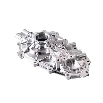
What This Page Covers
Prototype machining decisions for aluminum automotive parts, in the order they usually come up: alloy, geometry, fixturing, tolerance, finish, then the step to production.
Picking the Aluminum Grade for a Prototype
Most automotive prototypes start as a question about strength versus machinability. 6061-T6 is the default for brackets, housings, covers and motor mounts. It machines cleanly, welds, anodizes well, and you can buy it in plate and bar without a mill run. Yield strength is around 276 MPa, which is enough for most non-structural validation work.
When the part sees real load, 7075-T6 is the next step. Yield strength is roughly double that of 6061, so it suits suspension links, control arms and knuckles that will be driven hard. The trade-off is machinability: 7075 chips are shorter, tool wear is faster, and thin walls are more likely to move after machining. We usually leave more stock for stress relief and cut finishing passes lighter.
For parts that need corrosion resistance more than strength, 5052 and 5083 are common in brackets and panels. 2024 is used where fatigue life matters, though it needs a coating or anodize because it is not corrosion resistant on its own. Cast grades like ADC12 appear when the prototype is meant to validate a die-cast design before tooling.
If the prototype is a stand-in for a cast or forged production part, tell us at quote time. Machining from billet gives you different grain flow and different stiffness than a casting, and that changes how the part behaves in a test.
- 16061-T6General purpose. Brackets, housings, covers. Easy to machine and finish.
- 27075-T6High load. Suspension and steering parts. Slower to cut, needs care on thin walls.
- 32024Fatigue-critical parts. Requires anodize or coating for corrosion.
- 4ADC12Stand-in for die-cast designs before tooling is committed.
4-Axis and 5-Axis Setups for Auto Parts
Bearing bores, seal grooves and mounting faces usually need to be cut in one setup. That is the main reason 4-axis and 5-axis work shows up so often on aluminum alloy auto parts prototypes. Every refixture adds a small error, and on a bore that has to stay concentric with an outer diameter, those errors stack.
On a 4-axis mill with a Ø400 mm rotary table, we can index the part between faces and keep bores, slots and bolt patterns referenced to one datum. For a typical knuckle or housing, that means the bearing bore and the mounting face come off the same zero. Roundness and concentricity hold better, and the inspection report is easier to read.
Simultaneous 5-axis is reserved for parts with compound angles, deep pockets with drafted walls, or port geometry that a 3-axis tool cannot reach without a long, thin cutter. Long cutters deflect. On aluminum you might not see chatter, but you will see taper in a deep bore. Five-axis keeps the tool short and the load even.
Not every prototype needs 5-axis. A flat bracket with holes on one face is a 3-axis job and should be quoted as one. If we can cut it in three axes without losing tolerance, we will say so, because the setup cost is lower and the lead time is shorter.
What Tolerances to Call Out
A general tolerance block of ±0.1 mm across a drawing is normal for non-critical features. The parts that decide whether the prototype fits are usually a small number of dimensions: bearing bores, pilot diameters, dowel holes, seal seats and mounting hole patterns. Call those out individually and let the rest stay loose.
GreatLight machines to ±0.005 mm on critical features when the geometry and material allow it. That is not a default for the whole part. It applies to a bore or a face that has a real mating requirement. Tightening a whole drawing to ±0.005 mm raises cost and lead time without improving function.
Surface finish usually lands between Ra 0.8 and 1.6 μm for seal and bearing surfaces, with Ra 0.2–0.8 μm where a rotating seal runs. As-machined faces at Ra 1.6–3.2 μm are fine for covers and brackets. Finish callouts should match the function, not the habit of copying an old drawing.
Every part is inspected before shipment. Depending on the feature, that means a CMM report, bore gauge readings, or a first-article inspection sheet. Raw material certificates are checked on receipt, and in-process checks run during the cut. If you need a report format your quality team already uses, send it with the PO.
Prototype Machining Reference
Feature-specific starting points. Final values depend on geometry and alloy.
| Feature | Typical callout | Why it matters |
|---|---|---|
| Bearing bore | Ø tolerance ±0.005 mm, Ra 0.8–1.6 μm | Controls fit and running clearance |
| Bearing bore concentricity | 0.01 mm to mounting face | Prevents seal misalignment and vibration |
| Mounting hole pattern | Position ±0.05 mm | Bolt-up without slotting or reaming |
| Seal counterbore | Ra 0.2–0.8 μm, no chatter marks | Leak path forms at rough surfaces |
| General surfaces | ±0.1 mm, Ra 1.6–3.2 μm | Non-mating faces, no added cost |
| Wall thickness | 1.5 mm minimum in 6061 | Thin walls move after clamping release |
Finishes and Test-Ready Condition
Anodizing is the most common finish on aluminum prototypes. Clear anodize gives corrosion protection without hiding machining marks. Hardcoat builds a thicker oxide layer and improves wear resistance on sliding surfaces, but it adds a few micrometres per side, so bores with tight fits need masking or a pre-finish allowance.
Conductive anodize is used where the part has to ground through its mounting face. Electroless nickel goes on parts that need a hard, uniform layer with better dimensional control than hardcoat. Powder coating and black oxide show up on brackets and covers where appearance matters more than fit.
For engine and transmission prototypes, we often leave machined surfaces bare or lightly bead blasted so the engineer can read the surface after a test run. If a part will be cut open for inspection, tell us and we will skip the cosmetic finish.
Laser marking is available for part numbers and revision codes, with a minimum character height of 1.5 mm so the mark stays legible after anodize or paint.
When the Prototype Is Ready for Tooling
A machined prototype and a die-cast or forged production part are not the same thing. Before you commit to tooling, compare wall thickness, draft angle, corner radii and parting line location against what the casting or forging process can actually deliver. A 1 mm wall that machines fine may not fill in a die.
Use the prototype to confirm interfaces, not just shape. Bolt patterns, sensor mounting, bearing fits and clearance to neighboring parts are the things that cause rework later. If the prototype fits and runs, the production drawing should be updated from the as-machined dimensions, not the original CAD.
For low-volume builds or motorsport programs, machining from billet can carry the part well past the prototype stage. With no minimum order quantity, the same drawing can run from one piece to 10,000-plus parts, which keeps the validation and production geometry identical.
We can also review the design for manufacturing before you cut metal. Send the CAD and we will return a DFM note with the quote. If a feature will not hold tolerance or cannot be reached with a standard cutter, you will know before the first chip.
Common Questions
Can you machine a prototype from my STEP file without a 2D drawing?
Yes. We work from STEP, IGES and native CAD files, and we can build the drawing set from the model.
If tolerances are not specified, we apply a general tolerance and flag the critical features in the DFM note so you can confirm them before cutting.
How do you hold bearing bore concentricity on a one-piece prototype?
We cut the bore and the mating face in the same setup using a 4-axis or 5-axis machine, so both features share one datum.
Where the geometry allows, we also rough, stress-relieve if needed, then finish cut, which reduces movement after the clamps come off.
Which aluminum grade should I use for a part that will be track tested?
7075-T6 is the usual choice for loaded suspension and steering parts because of its higher yield strength.
6061-T6 is fine for brackets, covers and housings that do not see high cyclic load. Send the load case and we will give a recommendation with the quote.
Do you offer anodizing on prototype quantities?
Yes. Clear, color, hardcoat and conductive anodizing are all available on small runs.
Hardcoat adds thickness, so tell us which bores and faces must stay unmasked and we will set the pre-finish allowance accordingly.
What is the lead time for a prototype run?
Quotation and DFM analysis come back within 12 hours, and production can start within 24 hours of approval.
Parts typically ship in 3–5 days. Larger parts or multi-setup geometry take longer, and we will say so at quote time.
How is my design kept confidential?
Uploads are handled as confidential, and we can sign an NDA before you send files.
If you already have a mutual NDA, send it with the RFQ and we will review it.
Send Your Prototype Drawing
Upload your CAD and get a quote with DFM feedback within 12 hours.
12-hour quoteNo MOQIATF 16949:2016100% inspection









