Unlocking Peak Performance: The Lathe Operator’s Definitive Guide to Choosing Cutoff Tools
In the precision-driven world of turning, the "stop" operation – more technically known as cutoff or parting-off – is fundamental yet deceptively complex. Selecting the wrong parting tool can lead to chatter, broken inserts, ruined surface finishes, scrapped parts, and costly downtime. This guide distills the critical decision-making process into four powerful steps, moving beyond basic advice to deliver actionable insights forged on the shop floor. Master these, and you’ll transform a routine operation into a pillar of your machining efficiency.
Step 1: The Foundation – Shank Size & Machining Environment Mastery
Before considering the cutting edge, establish physical compatibility and prevent catastrophic interference.
Machine Interface is Paramount:
- Don’t assume standard sizes. Rigorously check your lathe’s turret or tool post specifications. Identify the exact mounting standard (e.g., VDI, BMT, CAT) and the maximum allowable shank height (H) and width (B). A tool exceeding these dimensions simply won’t fit.
- Consult the machine tool manual or measure existing, proven toolholders. This is the non-negotiable starting point.
- Workpiece Geometry Dictates Clearance:
- Material Diameter: This defines the primary cutting depth requirement for the tool. Measure the raw stock diameter at the cutoff location.
- Part Configuration & Chuck Jaws: This is the critical interference check. Visualize the tool’s path during the entire plunge.
- Where is the part relative to the chuck jaws or collet nose?
- Are there flanges, shoulders, or irregular shapes immediately adjacent to the cutoff?
- Consider chuck jaw thickness and potential protrusions like soft jaws or work stops.
- The Visualize-and-Measure Imperative: Before loading a tool, physically measure the toolholder’s head width, the insert’s projection, and its path relative to a dummy part setup or CAD model. Figure 1 (Imagine a toolholder profile overlaid on a part/chuck diagram) illustrates this clash check – an ounce of prevention here is worth pounds of scrapped parts and damaged tools.
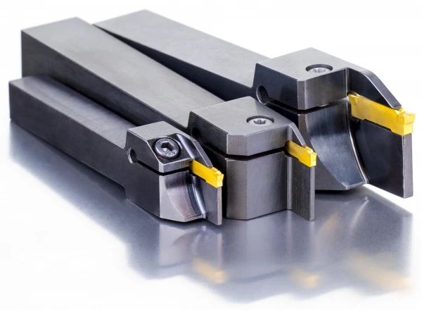
- Long Neck Holders – The Rigidity Savior for Tight Spots: When clearance between the chuck and guide bushing is minimal, or the part has low rigidity (thin walls, slender shafts), specify a long neck holder. Its extended reach allows cutting closer to the support while the robust shank section counteracts deflection that leads to chatter and poor surface finish.
Step 2: Direction Matters – Selecting Left-Hand vs. Right-Hand Orientation
It’s not just about spindle direction; it’s about strategic maneuverability.
- The Default: Right-Hand (RH) Design: The go-to choice. As the spindle rotates clockwise (M03), the tool plunges radially into the workpiece from the front. This is intuitive and suitable for the vast majority of applications.
- When Left-Hand (LH) Design Becomes Essential: Don’t force a RH tool into scenarios demanding its mirror image:
- Short Parts & Sub-Spindle Constraints: When machining very short components gripped solely in the sub-spindle, a RH tool mounted conventionally might physically collide with the main spindle housing during cutoff. Flipping to a LH tool allows clearance by approaching the part from the opposite side. (Figure 2: Sketch contrasting RH tool colliding vs. LH tool clearing main spindle).
- Live Tooling & C-Axis Machining: Lathes equipped with rotating tools (milling, drilling) often utilize a C-axis (spindle positioning). When performing cutoff operations combined with live tooling tasks, spindle direction (CW vs. CCW) might switch dynamically. A LH tool, paired with counter-clockwise (M04) spindle rotation, maintains the identical relative cutting motion and chip evacuation as a RH tool with M03. This prevents reprogramming headaches and potential tooling confusion during complex operations.
- Over-the-Top Gang Tool Setups: In gang tool configurations with extremely limited radial space, a LH tool mounted above the spindle centerline can provide the necessary clearance where a RH tool on the same post would interfere.
Step 3: Blade Geometry Demystified – Positive vs. Neutral (Negative) Rake Inserts
The shape of the cutting edge fundamentally controls forces, chip flow, and final quality.
- Neutral Rake (0° Rake, "Not Head-On"):
- The Workhorse for Stability:
- Robust Edge: The cutting edge sits directly on the insert centerline, maximizing support behind the edge. This inherently resists impact and shock loads common during heavier cuts, interrupted cuts, or with tougher materials (e.g., stainless steels, high-temp alloys).
- Linear Chip Evacuation: Chips flow straight down the V-groove flank. When properly controlled, this minimizes scratching or marring the freshly cut face of the part. Crucial for achieving fine finishes.
- Predictable Wear: Wear tends to progress more evenly across the cutting edge and flank face, often leading to longer, more predictable tool life under stable conditions. Excellent choice for general purpose cutoff, robust materials, and critical surface finish requirements.
- The Workhorse for Stability:
- Positive Rake ("Has an Angle on the Front"):
- The Finesse Option for Reduced Loads:
- Lower Cutting Forces: The angled cutting edge shears the material more efficiently, significantly reducing radial and tangential cutting forces. This is paramount for:
- Small Diameter Workpieces: Preventing part deflection or vibration (chatter).
- Low Rigidity Setups: Minimizing toolholder/boring bar deflection.
- Energy Savings: Reducing machine spindle load.
- Minimize Finish Burr: The sharper shearing action leaves a less pronounced burr on the parted-off surface, reducing secondary finishing needs.
- Lower Cutting Forces: The angled cutting edge shears the material more efficiently, significantly reducing radial and tangential cutting forces. This is paramount for:
- The Crucial Catch – Chip Control:
- Sideways Chip Hazard: The primary drawback. The positive angle causes chips to curl sideways into the insert’s V-groove flanks. Without exceptional coolant pressure/direction or chip breaker geometries specifically designed for positive rake parting, these spiraling chips are highly likely to scratch the critical cutoff surface. Best suited for smaller diameters, less rigid parts/mountings where force reduction is critical, but ONLY when chip control strategies (high-pressure coolant, specialized chip formers) are effectively implemented.
- The Finesse Option for Reduced Loads:
Step 4: Balancing Power & Precision – Optimizing Cutoff Blade Width
Width selection is a direct influencer of cutting forces, stability, and potential.
- Physics Dictates Loading: The force required to push the tool through the material increases significantly with a larger diameter. Cutting load is proportional to the width of the blade and the depth of cut (which is the radius).
- The "10% Rule" – A Starting Point, Not Gospel: Industry experience often suggests a blade width approximately 10% of the workpiece diameter. For a 50mm diameter part, a 5mm wide blade is a typical starting recommendation. Why?
- Provides sufficient mass and rigidity to handle the necessary cutting forces.
- Maintains adequate stability to minimize deflection and chatter.
- Allows for efficient chip flow through the insert groove.
- When to Deviate Strategically:
- Larger Diameters & Heavy Duty: Significantly exceeding 10% (e.g., 15-20%) may be necessary for:
- Very large diameters (>100mm)
- Challenging materials (stringy alloys, hardened steels)
- Applications requiring maximum tool rigidity and edge security. The wider land enhances damping.
- Smaller Diameters & Finishing Finesse: Slightly undersizing below 10% (e.g., 3mm for 40mm) can be advantageous for:
- Minimizing material waste (kerf loss).
- Reducing cutting forces and power consumption further (especially critical on smaller machines).
- Achieving finer finishes on very small parts where a wide blade might cause deflection.
- Larger Diameters & Heavy Duty: Significantly exceeding 10% (e.g., 15-20%) may be necessary for:
- Consult Your Tool Technology: Leading insert manufacturers engineer specific groove geometries optimized for particular width ranges. Leverage their application guides – a 3mm blade designed for parting will outperform a ground-down wider blade every time.
Beyond the Steps: The Art of Context
This 4-step framework provides the critical skeleton for parting tool selection. However, real-world mastery lies in layering context:
- Workpiece Material: Harder materials demand neutral rakes and wider blades. Softer, gummier alloys present chip control challenges that favor positive rakes only with excellent coolant strategy.
- Cutting Parameters: Speed (SFM) and feed rate directly interact with chip formation and heat. Typical parting feeds are often lower than turning feeds, but consistent feed is critical.
- Coolant Strategy: High-pressure, through-tool coolant is often the decisive factor enabling positive rake inserts or preventing chip jamming in neutral rake grooves.
- Machine Rigidity: An older or less rigid machine benefits immensely from a wider neutral rake blade to dampen vibration, whereas a new, high-rigidity lathe offers more flexibility with positive rake or narrower blades.
- Surface Finish Requirement: Demanding cosmetic faces may necessitate the forced linear chip flow of a neutral rake tool.
Conclusion: Precision Cutoff is Formula and Finesse
Selecting the optimal parting tool isn’t a checklist; it’s a calculated interplay between machine capabilities, part specifications, material science, and machining physics. By systematically navigating the critical choices of Shank Size & Clearance, Orientation, Insert Geometry, and Blade Width, you lay the groundwork for success. Remember the "10% width" and the stability-strength advantage of neutral rake inserts as foundational truths. Yet, embrace the nuance – knowing when to employ a left-hand tool or gamble on a positive rake for reduced deflection reveals true expertise. Apply this structured approach, validate with your specific conditions, dial in your parameters, and watch your cutoff operations transform from a necessary step to a benchmark of efficiency and quality. The path to flawless parting begins here.
