CNC Knowledge: Mechanical engineers must know what “central forest” is

WeChat picture_20250604104643.png

The Unseen Ally: Mastering Precision Drilling with Fixed-Point Commissions (And Preventing Costly Drill Wander) Drilling operations demand surgical accuracy. Yet, achieving a consistently precise hole—perfect size, depth, location, finish—often founders on hidden obstacles. Material inconsistencies, subtle surface imperfections, and the very geometry of the drill point conspire to cause the drill bit to "wander" at […]

Content Navigation

The Unseen Ally: Mastering Precision Drilling with Fixed-Point Commissions (And Preventing Costly Drill Wander)

Drilling operations demand surgical accuracy. Yet, achieving a consistently precise hole—perfect size, depth, location, finish—often founders on hidden obstacles. Material inconsistencies, subtle surface imperfections, and the very geometry of the drill point conspire to cause the drill bit to "wander" at the critical moment of initial engagement. This seemingly minor deviation can cascade into scrap parts, rejected batches, and costly rework. What’s the unsung hero preventing this costly drift? The fixed-point drill commission. When wielded strategically, it transforms precision drilling from a gamble into a science.

Section 1: At the Heart of Precision: Defining Drill Wander & the Fixed-Point Solution

Imagine striking a nail precisely: a clean hit drives it true. But if the hammer glances off slightly, the nail bends or veers off course. Drill wander occurs similarly on CNC machining centers. As the rotating drill touches the workpiece surface, uneven forces or an uneven surface can push the drill tip sideways before it bites deeply. The result? An oversized hole, a hole in the wrong location, potential tool breakage, or compromised surface finish—all violations of critical specifications.

The fixed-point drill commission (often called a "spot drill" or "center drill") acts as the ultimate drill pilot. Its singular mission: to create a precise, defined starting point for the main drill. By removing the variables of initial contact on the raw work surface, it anchors the drill tip, ensuring engagement begins exactly where programmed.

Section 2: Optimizing Performance: The Crucial Geometry of Angles

Simply using a fixed-point drill isn’t enough. Its geometry relative to the main drill bit dictates success or failure. The golden rule:

The fixed-point drill’s point angle MUST be equal to or (ideally) SLIGHTLY LARGER than the main drill’s point angle.

Why This Rule is Non-Negotiable:

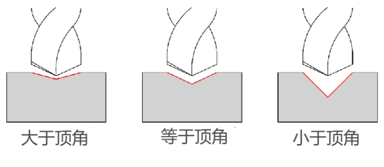
  1. Precision Guidance (Ideal Scenario – Larger Point Angle): When the spot drill angle exceeds the main drill angle, it creates a small, conical starting pocket perfectly matched to the drill’s center point. As the main drill engages, its point contacts the material first, precisely targeted within the conical recess. The outer lips of the drill only engage once the tip is secure, eliminating lateral forces that cause walking. This is the optimal setup for maximum accuracy and tool longevity.

    Visual Cue: Referencing Figure 1 (Left) in the source material, the diagram clearly shows the fixed-point drill creating a conical recess wider than the main drill’s point. The main drill tip finds its path unerringly.

  2. Acceptable Baseline (Equal Point Angle): Using a fixed-point drill with the exact same point angle as the main drill will provide significantly better starting consistency than no spotting at all. However, the outer cutting edges of the main drill will engage the material simultaneously with the center point. This offers no self-centering advantage and can subject the drill to slightly higher radial loads initially than a larger spot angle.

  3. The Dangerous Path (Smaller Point Angle): This is a primary cause of expensive tool damage and failed precision. A fixed-point angle smaller than the main drill’s angle creates only a shallow dimple. When the main drill feeds in, its outer cutting edges strike the untouched work surface before the center point makes significant contact.

    • Impact Load & Breakage: This acts like slamming a chisel sideways onto the drill tip. The sudden, uneven impact shock can instantly snap or chip the highly stressed outer corners of a carbide drill.
    • Reversed Purpose & Chatter: Instead of guiding the main drill, the shallow dimple created by the spot drill hinders it. The drill point lacks initial engagement depth and can vibrate or "chatter" wildly as it tries to establish its own path, milling away the spot drill’s marks and leading to poor hole quality. This renders the preceding spotting operation worthless and potentially damaging.

    Visual Cue: Figure 1 (Right/Center) illustrates this critical failure. The main drill’s periphery clashes with the unbroken surface because the small spot drill pocket doesn’t guide its tip effectively.

Section 3: Precision in Practice: Techniques Beyond Angles

  • The Mark of Excellence: The core purpose of a fixed-point drill is to create a starting point. However, technicians sometimes strategically employ it for a secondary function: creating a precise chamfer. By controlling the spot drill’s depth and potentially using a drill with a specific tip geometry, they can efficiently create the conical recess needed to perfectly seat a countersunk screw head flush with the surface. This is an advanced application leveraging the tool’s inherent precision for a secondary finishing step (See Fig 2 reference).
  • Surface Integrity Matters: Fixed-point commissions are most effective on relatively flat, stable surfaces. Irregular geometries pose a challenge:
    • Curved Surfaces: Drilling on the side of a cylinder introduces complex radial forces. The spot drill might create a valid divot, but as the main drill engages, unintended side loads from the curvature can still push it off-axis.
    • Slanted Planes: On an angle, gravity and the oblique surface feed direction conspire against alignment. A standard conical spot may not be sufficient.
  • Specialized Solutions for Irregular Surfaces: For curves, slants, or other complex surfaces where standard spotting falls short, flat-bottom drills offer a compelling alternative. These tools, as the name implies, feature a ground flat face underneath the cutting lips. This allows them to mill a small flat, perpendicular landing zone on the irregular surface first, providing a stable, level staging area for the main drilling operation and mitigating eccentric forces.

Section 4: Preventing the Shift: Integrating Fixed-Point Drilling into Workflows

The cost of drill wander is measured in scrap, time, efficiency loss, and premature tool failure. Integrating fixed-point commissions systematically offers robust ROI:

  1. Standardize the Optimal Geometry: Implement methodology: Select spot drills with a point angle consistently 0.5° to 1° greater than the primary drill bits used. Document and enforce this rule in setup procedures. Maintain a dedicated inventory of correctly angled spotting tools.
  2. Validate Surfaces: Assess workpiece surfaces pre-operations. For flat surfaces, standard spotting is king. Identify cylindricity or angularity before starting; switch to flat-bottom drills where necessary.
  3. Rigidity & Setup: Ensure workholding is secure and minimizes vibration. Slight workpiece movement during the initial spot drill operation defeats its purpose and compromises main drill accuracy. Overhang should be minimized.
  4. Controller Optimization: Leverage machine control features. Program spot drill feeds and speeds conservatively to prioritize precision placement. Ensure the Z-axis retract height after spotting is sufficient to clear the spot drill’s depth before moving to the main drill cycle.
  5. Tool Condition Monitoring: A dull or chipped spot drill is worse than useless – it can mislead the main drill or damage the surface. Include spot drills in the regular tool inspection and replacement schedule.

Conclusion: Precision is Not Optional – It’s Engineered

Drilling may appear straightforward, but achieving high-volume precision is a complex dance of metallurgy, mechanics, and geometric physics. Drill wander is a silent saboteur of quality and profitability. By mastering the science behind the fixed-point drill commission, understanding the critical interplay of angles, recognizing its limitations, and deploying it strategically on appropriate surfaces, manufacturers can transform their drilling operations from a potential failure point into a bastion of predictable, high-quality results. In the exacting world of CNC machining, eliminating the "slip" isn’t just good practice; it’s the fundamental marker separating competent work from truly engineered perfection.

Picture of JinShui Chen

JinShui Chen

Rapid Prototyping & Rapid Manufacturing Expert

Specialize in CNC machining, 3D printing, urethane casting, rapid tooling, injection molding, metal casting, sheet metal and extrusion

Pressroom

Recent Posts

Welcome to GreatLight Metal,Maximum Processing Size 4,000 mm

Precision Machining CNC Quote Online

Loading file

Upload Click here to upload or drag and drop your model to the canvas.

The model is too large and has been resized to fit in the printer's build tray. [Hide]

The model is too large to fit in the printer's build tray. [Hide]

The model is too large, a fitting printer is selected. [Hide]

The model is too small and has been upscaled. [Hide]

Warning: The selected printer can not print in full color [Hide]

Warning: obj models with multiple meshes are not yet supported [Hide]

Warning: Unsupported DXF entity  [Hide]

Warning: could not arrange models [Hide]


File Unit:      
Scale:
%
L × W × H:
X: × Y: × Z:  cm 
Rotation:
X: ° Y: °  


Model Stats:

Material Volume: cm3
Support Material Volume: cm3
Box Volume: cm3
Surface Area: cm2
Model Weight: g
Model Dimensions:
x x cm
Number of Polygons:
Number of Shapes:
Total Path: cm
⚡ Instant Quote for Precision Manufacturing

Submit your design files (STEP/IGES/DWG) and receive a competitive quote within 1 hour, backed by ISO 9001-certified quality assurance.

📋 How It Works

  1. Upload & SpecifyShare your 3D model and select materials (Aluminum/Stainless Steel/Titanium/PEEK), tolerances (±0.002mm), and surface treatments.

  2. AI-Powered AnalysisOur system calculates optimal machining strategy and cost based on 10+ years of automotive/aerospace data.

  3. Review & ConfirmGet a detailed breakdown including:
    - Volume pricing tiers (1-10,000+ units)
    - Lead time (3-7 days standard)
    - DFM feedback for cost optimization

Unit Price: 

Loading price
5 Axis CNC Machining Equipment
4 Axis CNC Machining Equipment
3 Axis CNC Machining Equipment
CNC Milling & Turning Equipment
Prototype and Short-Run Injection Moldings Exact plastic material as final design
Volume Metal Die Casting Services - Precision Cast Parts
Bridge the Gap From Prototype to Production – Global delivery in 10 days or less
Custom high-precision sheet metal prototypes and parts, as fast as 5 days.
Custom Online 3D Printing Services
Design Best Processing Method According To 3D Drawings
Alloys Aluminum 6061, 6061-T6 Aluminum 2024 Aluminum 5052 Aluminum 5083 Aluminum 6063 Aluminum 6082 Aluminum 7075, 7075-T6 Aluminum ADC12 (A380)
Alloys Brass C27400 Brass C28000 Brass C36000
Alloys Stainless Steel SUS201 Stainless Steel SUS303 Stainless Steel SUS 304 Stainless Steel SUS316 Stainless Steel SUS316L Stainless Steel SUS420 Stainless Steel SUS430 Stainless Steel SUS431 Stainless Steel SUS440C Stainless Steel SUS630/17-4PH Stainless Steel AISI 304
Inconel718
Carbon Fiber
Tool Steel
Mold Steel
Alloys Titanium Alloy TA1 Titanium Alloy TA2 Titanium Alloy TC4/Ti-6Al 4V
Alloys Steel 1018, 1020, 1025, 1045, 1215, 4130, 4140, 4340, 5140, A36 Die steel Alloy steel Chisel tool steel Spring steel High speed steel Cold rolled steel Bearing steel SPCC
Alloys Copper C101(T2) Copper C103(T1) Copper C103(TU2) Copper C110(TU0) Beryllium Copper
Alloys Magnesium Alloy AZ31B Magnesium Alloy AZ91D
Low Carbon Steel
Alloys Magnesium Alloy AZ31B Magnesium Alloy AZ91D
ABS Beige(Natural) ABS Black ABS Black Antistatic ABS Milky White ABS+PC Black ABS+PC White
PC Black PC Transparent PC White PC Yellowish White PC+GF30 Black
PMMA Black PMMA Transparent PMMA White
PA(Nylon) Blue PA6 (Nylon)+GF15 Black PA6 (Nylon)+GF30 Black PA66 (Nylon) Beige(Natural) PA66 (Nylon) Black
PE Black PE White
PEEK Beige(Natural) PEEK Black
PP Black PP White PP+GF30 Black
HDPE Black HDPE White
HIPS Board White
LDPE White
This is a finish of applying powdered paint to the components and then baking it in an oven, which results in a stronger, more wear- and corrosion-resistant layer that is more durable than traditional painting methods.
No coating required, product’s natural color!
This is a finish of applying powdered paint to the components and then baking it in an oven, which results in a stronger, more wear- and corrosion-resistant layer that is more durable than traditional painting methods.
This finishing option with the shortest turnaround time. Parts have visible tool marks and potentially sharp edges and burrs, which can be removed upon request.
Sand blasting uses pressurized sand or other media to clean and texture the surface, creating a uniform, matte finish.
Polishing is the process of creating a smooth and shiny surface by rubbing it or by applying a chemical treatmen
A brushed finish creates a unidirectional satin texture, reducing the visibility of marks and scratches on the surface.
Anodizing increases corrosion resistance and wear properties, while allowing for color dyeing, ideal for aluminum parts.
Black oxide is a conversion coating that is used on steels to improve corrosion resistance and minimize light reflection.
Electroplating bonds a thin metal layer onto parts, improving wear resistance, corrosion resistance, and surface conductivity.
This is a finish of applying powdered paint to the components and then baking it in an oven, which results in a stronger, more wear- and corrosion-resistant layer that is more durable than traditional painting methods.
Please provide additional text description for other surface treatment requirements!
Material
Material
  • CNC Metals
    • Aluminum
    • Brass
    • Stainless steel
    • Inconel718
    • Carbon Fiber
    • Tool Steel
    • Mold Steel
    • Titanium
    • Alloy Steel
    • Copper
    • Bronze
    • Low Carbon Steel
    • Magnesium
  • CNC Plastics
    • ABS
    • PC
    • PMMA (Acrylic)
    • PA (Nylon)
    • PE
    • PEEK
    • PP
    • HDPE
    • HIPS
    • LDPE
Printer
Printer
  • CNC Metals
    • 5 Axis CNC Machining
    • 4 Axis CNC Machining
    • 3 Axis CNC Machining
    • CNC Milling & Turning
    • Rapid Tooling
    • Metal Die Casting
    • Vacuum Casting
    • Sheet Metal Fabrication
    • SLA 3D Printing
    • SLS 3D Printing
    • SLM 3D Printing
  • Rapid Prototyping
    • Design Best Processing Method According To 3D Drawings
Post-processing
Post-processing
Finalize
The world's first CNC machining center that dares to provide free samples!

Free for first product valued at less than $200. (Background check required)

Precision Machining CNC Quote Online

15 Years CNC Machining Services

When you’re ready to start your next project, simply upload your 3D CAD design files, and our engineers will get back to you with a quote as soon as possible.
Scroll to Top

ISO 9001 Certificate

ISO 9001 is defined as the internationally recognized standard for Quality Management Systems (QMS). It is by far the most mature quality framework in the world. More than 1 million certificates were issued to organizations in 178 countries. ISO 9001 sets standards not only for the quality management system, but also for the overall management system. It helps organizations achieve success by improving customer satisfaction, employee motivation, and continuous improvement. * The ISO certificate is issued in the name of FS.com LIMITED and applied to all the products sold on FS website.

GreatLight Metal ISO 9001 certification successfully renewed
✅ ISO 9001:2015
GreatLight Metal ISO 9001 certification successfully renewed ZH

ISO 13485 certificate

ISO 13485 is an internationally recognized standard for Quality Management Systems (QMS) specifically tailored for the medical device industry. It outlines the requirements for organizations involved in the design, development, production, installation, and servicing of medical devices, ensuring they consistently meet regulatory requirements and customer needs. Essentially, it's a framework for medical device companies to build and maintain robust QMS processes, ultimately enhancing patient safety and device quality.

GreatLight Metal Technology Co., Ltd Has Obtained Multiple Certifications (3)
GreatLight Metal Technology Co., Ltd Has Obtained Multiple Certifications (4)

ISO 27001 certificate

ISO/IEC 27001 is an international standard for managing and processing information security. This standard is jointly developed by the International Organization for Standardization (ISO) and the International Electrotechnical Commission (IEC). It sets out requirements for establishing, implementing, maintaining, and continually improving an information security management system (ISMS). Ensuring the confidentiality, integrity, and availability of organizational information assets, obtaining an ISO 27001 certificate means that the enterprise has passed the audit conducted by a certification body, proving that its information security management system has met the requirements of the international standard.

GreatLight Metal Technology Co., Ltd Has Obtained Multiple Certifications (1)
GreatLight Metal Technology Co., Ltd Has Obtained Multiple Certifications (2)

IATF 16949 certificate

IATF 16949 is an internationally recognized Quality Management System (QMS) standard specifically for the automotive industry. It builds upon the foundation of ISO 9001 and adds specific requirements relevant to automotive production and service parts. The goal is to enhance quality, improve processes, and reduce variation and waste within the automotive supply chain.

Automotive Industry Quality Management System Certification_01
Automotive Industry Quality Management System Certification_00

Get The Best Price

Send drawings and detailed requirements via Email:info@glcncmachining.com
Or Fill Out The Contact Form Below:

All uploads are secure and confidential.