The characteristics of the automobile bogie shell are analyzed, processing tooling for the aluminum shell of the automobile bogie is introduced, which has been applied in production practice, and the tooling design points for this type of parts are summarized.
1 Preface
The automobile steering rack is an important part of the automobile steering system, providing a precise connection between the automobile steering wheel and the steering wheel. Among them, the bogie shell is an important component for the installation and fixing of bearings, worm gears, transmission shafts and other parts. Its function is to ensure the precise installation of bearings, the accuracy of the spacing of worm gears and worm gears, and stable output. of the transmission.
At the same time, it is necessary to ensure that the bogie is installed in the correct position on the car frame. The high mechanical precision of the bogie shell can avoid wear and damage of internal parts, extend the service life of the entire bogie, improve its operational efficiency, strengthen the rigidity of the bogie, and improve the response speed of the bogie. Therefore, the manufacturing precision of the bogie shell itself plays an important role in ensuring the above functions.
At present, most auto parts production equipment is equipped with CNC machine tools. The use of high-precision and multi-functional CNC machine tools simplifies tooling requirements, improves processing efficiency and reduces production costs. But this cannot be generalized. Sometimes, designing more complex tooling can reduce the performance requirements of CNC machine tools, thereby reducing processing costs.
Use it to improve treatment efficiency. This article is an obvious example. Although the five-axis multifunctional machining machine tool is powerful, according to the precision requirements of the processed parts, comprehensive consideration of processing efficiency, processing cost and other aspects, the use of general CNC machine tools combined with complex tooling can also optimize the best process solution. This paper proposes a more reasonable process solution by designing the bogie shell processing tooling and combining the existing production conditions of the enterprise.
2Characteristic analysis of hull parts
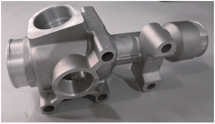
The bogie shell parts of the tooling to be designed and processed in this article are shown in Figure 1. The part is made of aluminum alloy and has an irregular shape. The batch blanks are poured into molds with good consistency. The part must be processed on 4 sides, of which the faces and holes in 1 direction must be processed at a rotation angle. Figure 2 is a two-dimensional diagram of the part. The positions of the boxes in the diagram correspond to the four directions that need to be addressed.
Figure 1 Bogie shell parts

Figure 2 2D drawing of parts
The processing requirements of this part are mainly bearing planes and holes in 4 directions.[1]Dimensional tolerance 0 ~ 0.02mm. The angle and tolerance of the angular surface is 16° ± 3′, and the distance tolerance between the axis of the characteristic round hole on this surface and the horizontal axis is 0 ~ 0.05mm. It can be seen from the figure that the processing precision of this part is not very high. The main processing complexity lies in multi-faceted processing and special-shaped clamping. If you use a three-axis machine tool for processing, you need to create multiple tool sets and complete them in 4 processes. However, when determining the method of clamping parts, care should be taken to reduce the number of times[2]. If a five-axis machine tool is used for positioning processing, it can be completed in one clamping, but the efficiency is low and the cost is high. This part also used five-axis positioning processing during the trial production process. In combination with the company’s production site conditions and mass production conditions, it was decided to use the exchange workbench of a horizontal machining center to carry out the two-step processing. Make two toolings, one tooling completes the processing of three mutually perpendicular surfaces, and the other tooling is responsible for processing the angular direction of the surface, thereby achieving uninterrupted production of products, greatly improving efficiency.
3 Design of processing tools
According to the analysis of the above shell parts, two processes can be used to complete the processing on the horizontal machining center. The first process (process 1) finishes processing the three sides of the box 1, 3 and 4 shown below. Figure 2, and a tooling assembly can be designed.
(Tooling 1), installed on table A of the horizontal machining center. The second process (process 2) completes the processing of the angular characteristic surface of the box 2, using the second set of tools (tooling 2) installed on the workbench B of the horizontal machining center. This tooling design was carried out using CimatronE software, which is characterized by strong CAD and CAM integration.[3]can be easily designed and manufactured.
3.1 Design of tooling 1
Tool 1 mainly completes the processing of three sides of the workpiece. The three sides are 90° to each other, which can be completed by rotating the angle of the horizontal machining center worktable. In order to improve efficiency, three parts are placed on the tooling to be processed at the same time according to the stroke of the existing machine tool.[4]。
First, a tooling column is designed, and the three parts are evenly distributed in the height direction of the column. Assemble 3 support plates on the tooling column, and place the 3 shell parts on the support plates, as shown in Figure 3.

Figure 3 Process 1 tool design
1—Base plate 2—Column 3—Reinforcement ribs 4—Parts 5—Pressure plate 6—Support plate
The design points are as follows.
1) In order to facilitate the assembly and maintenance of the tooling, pins are used to position each part of the tooling and are tightened by bolts.[5]. The support plate must have a certain thickness to ensure a sufficiently large mounting surface. As shown in Figure 3, pins are used to position the three support plates and columns, and they are secured with four high-strength M10 bolts. The base plate and column are positioned with 2 φ10mm pins and 4 M12 high strength hexagon head bolts. Since the dimensions of the column are 100mm in length, 80mm in width and 420mm in height, reinforcing ribs are added between the base plate and the column to improve the overall rigidity. In actual processing, it is fully proven that the rigidity fully meets the requirements.
2) The product shell parts are installed and positioned on the support plate according to the 6-point positioning principle (see Figure 4). Since the parts are special shaped parts cast in molds, the parts have good shape consistency, but there is no complete, regular plane on which to install the supports, so three small protrusions are designed on the support plate, which is equivalent to setting up. The parts and forming an imaginary positioning surface serves as support, which limits the part to three degrees of freedom (see the three-point positioning position of the bottom surface in Figure 4). Small stops are placed in the left and right directions on the support plate. When installing parts, the degree of freedom of movement left and right can be limited by being close to them (see the left and right positioning positions in Figure 4). At the same time, two positioning blocks are placed on the column and the workpiece is firmly fixed here to limit the two degrees of freedom of forward and backward movement and rotation (see positioning position on the column in Figure 4).

Figure 4 6-point positioning diagram on the support plate
3) The hull parts are tightened using pressure plate bolts. Once the parts are installed and positioned, 3 sets of pressure plate bolts are used for tightening. The clamping position coincides with the three small raised support points, as shown in Figure 5. This prevents the aluminum part from deforming when clamping.

Figure 5 The position of the pressure plate corresponding to the point of support
3.2 Design of tooling 2
Tooling 2 is mainly used to process the workpiece of the box 2 shown in Figure 2, and the processing content is mainly the angular plane and hole in this workpiece. The position accuracy that must be guaranteed is 16°±3′, and the position tolerance of the distance between the hole axis and the horizontal axis is 0~0.05 mm. Dimensional accuracy includes hole diameter and thread accuracy.
The positioning of processed parts in tooling 2 adopts the method of 2 spindles combined with 1 plane. Placing the plane processed in step 1 (see box 4 in Figure 2) as a reference on the horizontal plane of the tooling can limit the three degrees of freedom of the part: up and down movement, forward and backward rotation, left and right. rotation. Design two positioning pins on the horizontal plane of the tooling (one is a cylindrical pin and the other is a diamond pin to improve positioning accuracy and facilitate installation), and use two auxiliary reference holes on the part to cooperate with them to limit the forward, backward, left and right movement of the part and 3 degrees of freedom of rotation in the horizontal plane. Auxiliary reference holes use existing holes on the part (see Figure 6), which have no requirement for accuracy in the drawing. In order to ensure accurate positioning in process 2, the two holes that should be used as reference holes are. finely machined, and the dimensional accuracy is φ![]() . Once the parts are positioned on the tooling, they are tightened using pressure plates and bolts.
. Once the parts are positioned on the tooling, they are tightened using pressure plates and bolts.

Figure 6 Schematic diagram of auxiliary reference hole
For position accuracy of 16°±3′, when designing, consider forming an angle of 16° between the centerline of the two locating pins on the tooling and the X-axis direction of the machine- tool. Once the part is positioned, the workpiece is positioned. The plane formed after moving the tool along the X axis is naturally ensured. Make sure the included corner size requirements are met. For the angular tolerance of ±3′, as mentioned above, the diameter of the two auxiliary reference holes on the part after finishing in step 1 is![]() the spacing is the sum of the two dimensions 51.5 mm and 56 mm, guaranteed to be (107.5 ± 0.01) mm. The diameter of the two locating pins on the tooling is 9.98 mm and the distance is guaranteed to be (107.5 ± 0.01) mm. There is clearance between the locating holes and the pins, and the gap is guaranteed to be within 0.03. mm. Through trigonometric calculation, 107.5×tan3’≈0.094 (mm), that is, the vertical oscillation error of the two pinholes at a distance of 107.5mm can ensure accuracy of ±0.094 mm. The position and dimensional accuracy of pins and holes after machine tool processing can fully meet the above-mentioned error range, meet the process requirements of tooling, and ultimately guarantee that hull parts are positioned on tooling and processed to meet model tolerance requirements. Tooling for process 2 is shown in Figure 7.
the spacing is the sum of the two dimensions 51.5 mm and 56 mm, guaranteed to be (107.5 ± 0.01) mm. The diameter of the two locating pins on the tooling is 9.98 mm and the distance is guaranteed to be (107.5 ± 0.01) mm. There is clearance between the locating holes and the pins, and the gap is guaranteed to be within 0.03. mm. Through trigonometric calculation, 107.5×tan3’≈0.094 (mm), that is, the vertical oscillation error of the two pinholes at a distance of 107.5mm can ensure accuracy of ±0.094 mm. The position and dimensional accuracy of pins and holes after machine tool processing can fully meet the above-mentioned error range, meet the process requirements of tooling, and ultimately guarantee that hull parts are positioned on tooling and processed to meet model tolerance requirements. Tooling for process 2 is shown in Figure 7.

Figure 7 Tooling for process 2
Other dimensions such as center spacing and hole diameter can be fully guaranteed by the precision of the machine tool.
4 Comparison of treatments
4.1 The product is trial-made and processed in the five-axis machining center
Figure 8 shows the state of the part being machined on a five-axis machining center. The entire processing content can be completed with a single tightening operation.

Figure 8 Using a five-axis machining center to process parts
The advantages of this treatment method: ① Simple tools. ②High precision. ③The operating intensity of the operator is low. Disadvantages: ① Low efficiency. ②The processing cost is high.
4.2 Use tools for batch processing on horizontal machining centers
Figure 9 shows the processing of Process 1 performed on a horizontal machining center. The advantages of this treatment method: ① High efficiency. ② Low processing cost. ③The processing accuracy meets the requirements. Disadvantages: The tooling is complex.

Figure 9 Processing Process 1 Using a Horizontal Machining Center
4.3 Comparison of treatments
As it takes 20 minutes to produce 3 parts using horizontal machining center, the processing time of each product is only 6-7 minutes and the workpiece can be clamped on the worktable ‘exchange without stopping, so the production efficiency is high. The five-axis machining center takes 12 minutes to process each part and must stop for each part replacement. In addition, the labor cost of a five-axis machining center is 2-3 times that of a horizontal machining center, so a horizontal machining center is suitable.
5Conclusion
1) Based on the comparison of the actual processing process, the tooling designed in this article is easy to install, strong in rigidity and high in efficiency, and the processing precision of the workpiece fully meets the requirements of the drawing.
2) For cast aluminum parts, when designing tooling, to avoid deformation caused by clamping, try to use 3-point supports (additional attention will be paid to hydraulic floating supports at the same time, at the point of pressure tightening). the plate must coincide with the support point. Although castings and die castings have the same exterior dimensions in theory, they are actually distorted if more than 4 points of support and clamping are used, clamping distortion will occur due to excessive positioning and the Machining accuracy will be affected subsequently. the pressure plate is released after treatment. At the same time, the area of the three support points themselves should be as small as possible to avoid compression deformation caused by large areas.
Daguang focuses on providing solutions such as precision CNC machining services (3-axis, 4-axis, 5-axis machining), CNC milling, 3D printing and rapid prototyping services.


