
60m CNC Machining Radiator Parts: Tips That Hold Up on the Floor
This page covers how to plan 60m CNC machining radiator parts so the fins, channels and sealing faces come off the machine usable. It is written for design engineers and manufacturing engineers who need to judge material, geometry and process selection before sending a drawing out. Read it and you can tell which radiator parts belong on a mill, which belong on a mill-turn, and where the tolerance budget actually goes.
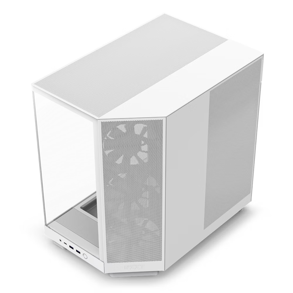
What a radiator part asks of a CNC machine
Radiator parts are mostly about surface area, sealing, and keeping thin walls from moving.
Material choice sets the machining strategy before you choose a cutter
Radiator parts live or die by thermal conductivity, but the shop has to cut them too. Aluminum alloys such as 6061, 6063 and 6082 give a good balance: thermal conductivity around 150–200 W/m·K, free machining, and low weight. Copper C101 or C110 roughly doubles that conductivity, and it also doubles the trouble. Copper grabs tools, builds heat, and needs sharp carbide and generous coolant.
Pick copper when the heat flux is high and space is tight, for example in power electronics cold plates or laser diode housings. Pick aluminum when the part is large, weight matters, or the budget is fixed. A copper radiator that costs four times as much and takes twice as long to machine is rarely the right answer for a 200 W load.
There is a middle path. Copper alloys such as C27400 or beryllium copper machine better than pure C101 while keeping decent conductivity. On the aluminum side, ADC12 die casting stock and 7075 are available if the part needs higher strength, though 7075 conducts less heat than 6061. Match the alloy to the thermal job, not to the shelf.
- 1Aluminum 6061 / 6063 / 6082Default for most liquid and air-cooled radiator bodies. Easy to machine, anodizes well.
- 2Copper C101 / C110Highest conductivity. Use for tight, high-flux cold plates. Expect slower cycles.
- 3Copper C27400 / BeCuBetter machinability than pure copper, still good heat transfer.
- 4Stainless 304 / 316LPoor conductor. Choose only when corrosion resistance outweighs thermal performance.
Fin geometry and wall thickness decide whether the part survives the vise
Thin fins are the point of a radiator, and they are also the reason parts get scrapped. A fin 0.8 mm thick and 20 mm tall will deflect under cutting force and sing like a tuning fork. The fix is not a slower feed alone. Support the fin with a sacrificial web, machine the channels in a sequence that leaves stiffness until the last pass, or flip the part and take the fin side in a second operation.
As a working rule, keep fin thickness at 1.0 mm or above for aluminum unless the design truly needs thinner. Aspect ratio matters more than absolute thickness: a 0.8 mm fin that is 8 mm tall is far easier than a 0.8 mm fin that is 25 mm tall. If the thermal calculation demands the tall thin version, plan for a support structure and accept the extra deburring step.
Channel width and depth also drive tool choice. A 2 mm wide channel 10 mm deep needs a 2 mm end mill with a length-to-diameter ratio of 5:1. That tool will deflect. Either widen the channel, reduce the depth, or split the feature across two setups so the tool reaches only half the depth at a time.
- 1Fin thickness1.0 mm minimum for aluminum in normal production. Thinner needs support and slower passes.
- 2Aspect ratioKeep fin height under 10× thickness where possible.
- 3Channel depthKeep tool length-to-diameter under 5:1 to control deflection.
- 4SequenceRough the stiff side first, then remove support webbing last.
Radiator part types and the process that fits
Use this to sanity-check a design before quoting.
| Part type | Typical material | Process | Watch out for |
|---|---|---|---|
| Flat cold plate | Aluminum 6061 | 3-axis mill | Flatness on the sealing face |
| Fin stack housing | Aluminum 6063 | 4-axis mill | Fin deflection during cutting |
| Cylindrical radiator body | Aluminum 6082 | Mill-turn | Concentricity of bore to fins |
| High-flux copper cold plate | Copper C110 | 3-axis mill | Tool wear and heat buildup |
| Manifold with angled ports | Aluminum 6061 | 5-axis mill | Port position after two setups |
| Thin-wall housing | Aluminum 5052 | 3-axis mill | Wall collapse from clamping |
Where the tolerance budget should go, and where it should not
A radiator drawing often carries one blanket tolerance across every feature. That is expensive and usually unnecessary. The sealing face, the mounting hole pattern and any mating bore need tight control. Fin tips, outer profile and non-critical pockets do not. Splitting the drawing into tight and free zones lets the shop run faster on the free zones and spend the time where it changes function.
GreatLight holds ±0.005 mm on critical features, but we do not apply that to every surface. A sealing face machined to Ra 0.8–1.6 μm gives a reliable gasket or O-ring seat. A fin surface at Ra 1.6–3.2 μm is fine for air flow and cheaper to produce. As-machined finish is often the correct call for internal channels that nobody sees.
Flatness deserves its own note. A cold plate that is 200 mm long and warps 0.1 mm after machining will leak no matter how good the surface finish is. Stress relief before finishing, light finishing cuts, and letting the part cool before the final pass all help. On large plates, we sometimes rough, stress relieve, then finish.
- 1Tight zoneSealing faces, O-ring grooves, mounting holes, mating bores.
- 2Free zoneFin tips, outer profile, non-mating pockets, internal channel walls.
- 3FlatnessCall it out explicitly on sealing faces. Do not rely on a general tolerance.
Setup count and 5-axis: when the extra axis pays for itself
Every additional setup adds error. A radiator body with ports on four sides and a sealing face on a fifth will need multiple operations on a 3-axis machine. Each flip re-datum the part, and each re-datum adds stack-up. A 5-axis machine can reach those faces in one or two setups, which often removes more cost than the higher hourly rate adds.
The decision is not about part complexity in the abstract. Count the faces that need machining and the angle between them. Two faces at 90° are fine on a 3-axis with a vise. Five faces at odd angles, or a curved sealing surface, push toward 5-axis. GreatLight runs 16 simultaneous 5-axis centers with a Ø400 mm rotary table, plus 16 mill-turn centers for parts that are mostly round.
For round radiator bodies with fins and a central bore, mill-turn is usually the better answer than a 5-axis mill. Turning holds concentricity between the bore and the outer diameter in a single setup. Milling the fins on the same machine avoids a second datum. If the drawing shows a round body with a tight bore-to-OD relationship, ask for mill-turn.
- 13-axisFlat plates, single-face pockets, simple housings. Fewest setups means lowest cost.
- 24-axisParts with features on multiple sides of a prismatic block.
- 35-axisAngled ports, curved sealing faces, complex manifolds.
- 4Mill-turnRound bodies with a bore and external features that must stay concentric.
Finishing choices that help heat transfer and those that only look good
Anodizing is the default finish for aluminum radiator parts. Clear anodize adds mild corrosion protection and does not hurt thermal performance much. Hardcoat anodize builds a thicker oxide layer that is more wear resistant, but that layer is also a thermal insulator. On a fin surface, a thick hardcoat can measurably reduce heat transfer. Use it on wear surfaces, not on the fins.
Conductive anodize exists for a reason: it keeps the corrosion protection while leaving the surface electrically conductive. That matters when the radiator is also a grounding path. Electroless nickel and silver plating are options for copper parts that need corrosion resistance without a heavy oxide layer.
Bead blasting and brushing change the surface texture. On an external air-cooled radiator, a slightly rougher surface can increase effective area, but the gain is small and hard to predict. Do not specify a texture for thermal reasons unless the numbers back it up. Specify it for appearance or for adhesion before coating.
- 1Clear anodizeGood default for aluminum. Thin oxide, minimal thermal penalty.
- 2Hardcoat anodizeUse on wear surfaces only. Thick oxide insulates.
- 3Conductive anodizeWhen the part must stay grounded.
- 4Electroless nickelCopper parts needing corrosion resistance.
Questions engineers ask before releasing a radiator drawing
What is the thinnest fin you can machine reliably in aluminum?
One millimeter thick is a comfortable production limit for aluminum fins up to about 10 mm tall. Below that, deflection and chatter become the limiting factor rather than the tool.
If the thermal design needs 0.5 mm fins, we can still cut them, but expect support webs, slower passes, and a deburring step. Send the drawing and we will tell you where the risk sits.
Should I specify copper or aluminum for a liquid cold plate?
Copper wins on conductivity, roughly twice that of aluminum. It loses on machinability, tool wear, weight and cost. For loads under a few hundred watts in a well-designed plate, aluminum 6061 usually meets the thermal target.
Copper makes sense when the heat flux is concentrated in a small area or the available volume is fixed. If you are unsure, we can quote both and you can weigh the cycle time difference.
How do you keep a long cold plate flat during machining?
Stress relief before finishing is the main control. We rough the plate, relieve stress, then take light finishing cuts with the part allowed to reach room temperature before the final pass.
Clamping also matters. Heavy vise pressure on a thin plate springs it, and it returns to a warped shape after unclamping. We use low-pressure fixturing or vacuum for thin plates.
Can you machine the sealing groove and the fins in the same setup?
Often yes, if the geometry allows the tool to reach both from one direction. That keeps the groove and the fin face in the same datum, which helps flatness and seal reliability.
When the fins are on the opposite side of the plate, a second setup is unavoidable. In that case we machine the sealing face last so any minor distortion from the first operation is removed.
What surface finish should I call out on a sealing face?
Ra 0.8–1.6 μm is a practical target for gasket and O-ring seats. It is smooth enough to seal and still economical to produce.
Ra 0.2–0.8 μm is available when the seal is critical or the media is aggressive. It costs more because it needs a separate finishing pass and sometimes a different tool.
Do you need a 3D model, or is a 2D drawing enough?
A 3D model plus a 2D drawing with tolerances is the cleanest input. The model defines the shape, the drawing defines what matters.
A 2D drawing alone works for simple plates. For angled ports or curved channels, a model saves time and reduces the chance of a misread feature.
Send us the radiator drawing and we will tell you what it takes
We review the geometry, flag the thin features, and come back with a process plan and a quote. Uploads stay confidential, and an NDA is available on request.
12-hour quoteFree DFM analysis100% inspection









