
5 Secret 3D Printing Techniques Every Enthusiast Must Know
Most of the secret 3D printing techniques that matter are not hidden in the printer menu. They sit in the workflow around the machine: how you slice, how you handle powder, how you cure, how you monitor, and how you finish. This guide is for engineers and buyers who need printed parts that mate with machined ones.
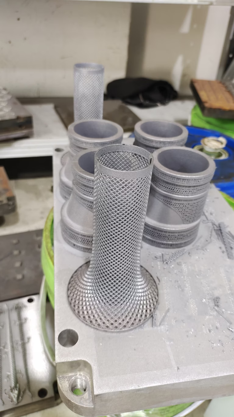
What separates a printed prototype from a printed part
Each technique below is judged on one question: does it change whether the part fits and works in an assembly?
Variable-layer adaptive slicing: quality where it shows, speed where it does not
Most desktop slicers ship with one fixed layer height, often 0.2 mm. That is easy to reason about, and it wastes time on geometry that does not need it. A vertical wall does not care whether layers are 0.1 mm or 0.3 mm. A shallow dome does. When you let the slicer vary layer height within the same part, thin layers go only where curvature or a visible surface demands them.
The gain is real but bounded. On a part with mixed features, dropping from a constant 0.2 mm to a range of 0.12–0.28 mm typically cuts build time by 15–30% while holding the visible faces at the finer end. Below 0.08 mm the nozzle spends more time moving than extruding, and the surface stops improving. Increase minimum layer time so each thin layer cools before the next one lands.
One limit is worth stating plainly. Adaptive slicing improves the printed surface only. It cannot make a flat mating face flat, and it cannot hold a threaded hole or a press-fit pin. Those features need a cutting tool. In our shop, printed brackets and robot end-effectors get their reference faces and bores finished on the machining centers, because a printed datum is not a datum.
- 1Set a floorNever go below 0.08 mm layer height; cooling time, not resolution, is the bottleneck.
- 2Keep the top face fineForce thin layers on any surface the customer will see or touch.
- 3Machine the interfacesBores, threads and press fits belong on a mill, not in a slicer profile.
Powder management in SLS and metal printing
In powder-bed processes the material is not just feedstock, it is also support structure. That makes powder condition a process variable, not a consumable. Every build cycle heats the bed, and the powder that was not melted picks up moisture, oxygen and fine satellite particles. Reuse it without control and the next part sinters differently.
The practical rule is to track the ratio of used to virgin powder and keep it inside a qualified window. For polymer SLS, blending 30–50% used powder with virgin material is common; the exact ceiling depends on your mechanical requirements. Metal systems are stricter. Titanium and aluminium powders react with oxygen, so sieve them, check the particle size distribution, and retire batches before chemistry drifts.
This is where a hobby machine and a production cell diverge. A desktop SLS printer with a sealed hopper can run the same blend for months. A metal system needs an inert atmosphere, a sieve station and logged batch history. If a printed part has to pass a fatigue or pressure test, the powder log is part of the traceability package.
Grayscale masking and sub-pixel curing in resin printing
Resin printers expose a whole layer at once through an LCD or DLP mask. The trick most users miss is that the mask has more than two states. A pixel can be full black, full white, or partially transparent. Use the gray values and you can soften edges, reduce the peel force on fine features, and control cure depth across a single layer.
Sub-pixel rendering pushes this further. By shifting the projected image by half a pixel between exposures, the printer builds an effective resolution finer than the physical pixel grid. Sharp corners stop blooming, and small holes stay round instead of squaring off. The cost is exposure time: two shifted exposures take longer than one.
Both techniques only help features the light can reach. Internal channels, trapped volumes and anything that needs a tight tolerance still get resolved in post-processing or on a mill. We treat the print as near-net shape and cut the critical dimensions afterward, which is why we keep five-axis centers next to the resin printers.
Closed-loop process monitoring, not just filament monitoring
Filament runout sensors and spaghetti detection are entry-level. They tell you something went wrong after it already went wrong. Industrial monitoring watches the process signature: melt pool temperature in metal systems, laser power and scan speed in powder beds, layer images in resin, extrusion force in FDM.
For metal printing the useful signals are melt pool intensity and build plate position. A drift in either usually means the part is deviating before the surface shows it. For resin, per-layer imaging catches a failed support or a detached part on the layer it happens, not six hours later. Both approaches cut scrap, and both produce a log you can hand to a customer.
The honest limit is that monitoring detects deviation; it does not correct it. A closed-loop metal system can adjust laser power in real time. A resin printer can only pause. Know which one you are buying before you promise a tolerance.
Hybrid additive and subtractive completion on five-axis machines
The most useful technique on this list is also the least glamorous: print the part, then machine the features that must be accurate. Additive builds the shape. Subtractive creates the datum. A printer can hold a wall thickness to a few tenths of a millimeter; it cannot reliably hold a bore to ±0.005 mm.
The workflow is straightforward. Print with machining allowance on any face that will be a reference. Mount the part on a fixture, probe it to find the actual printed surface, and cut the datums, bores, threads and sealing faces. On a simultaneous five-axis center you can reach undercuts and angled faces in one setup, which matters when the part is a thin bracket that would distort if you moved it.
This combination is how printed prototypes become functional hardware. It is also how you avoid the common failure mode of a beautiful print that will not bolt to anything.
Which technique fits which part
Match the technique to the feature that actually decides whether the part works.
| Technique | Best for | Not suitable for | Typical gain |
|---|---|---|---|
| Adaptive slicing | Curved shells, visible faces, mixed geometry | Flat mating faces, threads, press fits | 15–30% less build time |
| Powder management | SLS and metal runs with reused powder | One-off builds with virgin powder only | Stable mechanical properties |
| Grayscale curing | Fine resin features, small holes, sharp corners | Thick solid sections, internal channels | Finer effective resolution |
| Closed-loop monitoring | Metal and resin production runs | Hobby printers without sensors | Lower scrap, traceable logs |
| Hybrid printing plus CNC | Bores, datums, sealing faces, threads | Parts with no critical interface | ±0.005 mm on cut features |
Process capability at a glance
Numbers we can hold in our own shop, from printing through finishing.
| Item | Capability | Notes |
|---|---|---|
| Machined tolerance | ±0.005 mm | On cut features, not as-printed surfaces |
| Fine surface finish | Ra 0.2–0.8 μm | Requires polishing or fine milling |
| Standard machined finish | Ra 0.8–1.6 μm | Typical for functional interfaces |
| Maximum part size | 4,000 mm | On the largest machining travel |
| Five-axis centers | 16 simultaneous | For undercuts and angled faces |
| Order quantity | One piece to 10,000+ | No minimum order quantity |
Common questions
Can adaptive slicing replace machining on a mating face?
No. Adaptive slicing changes layer height, not the geometry of a flat surface. A printed face still carries layer lines and a small taper from the extrusion or sintering process.
If the face locates another part, cut it. We print with allowance and machine the datum, which is why the printed part and the finished part are not the same model.
How much used powder can be blended back in?
For polymer SLS, 30–50% used powder with virgin material is a common working range. The correct ceiling depends on the mechanical properties your part needs.
Metal powders are stricter. Oxygen pickup and particle coarsening change the melt behavior, so sieve, test and retire batches on a logged schedule rather than on visual inspection.
Is grayscale masking worth it on a desktop resin printer?
It depends on the feature size. If your smallest hole is 2 mm or larger, the gain is small. If you are printing 0.5 mm holes or thin fins, it reduces blooming and keeps edges sharp.
Sub-pixel shifting costs exposure time, so run it on the layers that need it rather than the whole part.
What does closed-loop monitoring actually log?
Melt pool intensity, laser power, scan speed and build plate position for metal systems. Layer images and peel force for resin. Extrusion force for FDM.
Those logs are useful for traceability and for catching drift early. They do not correct every deviation, so pair them with dimensional inspection on the finished part.
When should a printed part go to a five-axis machine?
Any time it has a bore, a thread, a sealing face, a press fit or a datum that another component references. Also when the printed surface would distort under a clamp load.
If the part is purely cosmetic or a fit-check model, printing alone is fine and faster.
What information do you need to quote a hybrid print-and-machine job?
A 3D model, the critical dimensions and their tolerances, the material, and which faces are functional. Tell us which features must be machined and which can stay as printed.
We return a quotation and a DFM analysis, usually within 12 hours, and production can start within 24 hours after approval.
Send us the part that has to fit
Upload a model and tell us which features are critical. We will confirm the print-and-machine route and quote it.
12-hour quote±0.005 mm100% inspectionNDA on request









