
5 Metal 3D Printing Updates in Additive Manufacturing Today
This page is for design engineers and sourcing engineers who already know powder bed fusion basics and want to know what actually changed on the shop floor. We cover multi-laser scanning, new alloy powders, in-process monitoring, hybrid AM plus CNC routing, and powder reuse. After reading, you should be able to tell which parts belong on a metal printer and which belong on a mill.
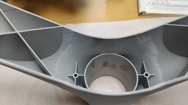
What changed, and why it matters to a print decision
Five shifts that moved metal AM from one-off prototypes to repeatable production parts, plus the cases where it still loses to machining.
Multi-laser machines are now the default for production builds
A single 200 W to 400 W laser scanning a powder bed line by line is slow. A medium bracket could take days, which made the process hard to justify beyond prototypes. Current SLM machines run two, four, or six lasers over the same build plate, and the scan strategy splits the part cross section between them. Build time drops sharply, though the exact gain depends on how much of the layer is solid metal.
The catch is heat interaction. When two lasers work on adjacent areas at the same time, the melt pools can overlap and residual stress builds unevenly. Independent beam control and corrected optics reduce this, but the scan order still has to be tuned per alloy and per geometry. A thin-walled heatsink and a solid manifold do not share the same recipe.
For a buyer, the practical effect is that low-volume production runs become viable. Ten to two hundred units of a stainless or aluminum part can ship in days instead of weeks, and the per-part cost falls because machine time per build is shorter. It still is not a replacement for a 10,000-piece die casting run.
New alloy powders widen the material list
The old menu was mostly 316L, Ti-6Al-4V, and a few tool steels. That list has grown. Printable copper and copper-chromium-zirconium grades now make induction coils and heat spreaders possible, where the thermal conductivity of the printed part beats what you get from a machined copper block with brazed joints. High-strength aluminum grades with better crack resistance are also available for thin walls that used to fail during the build.
Nickel alloys such as Inconel remain the choice for hot sections, and 17-4PH stainless is common where you need hardness plus corrosion resistance after heat treatment. The tradeoff is that each powder has its own laser power, layer thickness, and support rules. A material that prints well at 30 μm layers may be slow and porous at 60 μm.
Before you design around a new alloy, ask for the powder specification and the heat treatment schedule. Printed material is not identical to wrought. Porosity, grain structure, and surface roughness all differ, and that changes fatigue behavior. If the part is flight-critical or implantable, the qualification path is longer than the design path.
In-process monitoring moved quality from inspection to prediction
Melt pool monitoring, layer imaging, and machine data logging are now standard on mid-range and high-end metal printers. The machine records what happened layer by layer, so a defect can be traced to a specific position and time rather than found later in a CT scan. That shortens the loop between a bad build and a corrected recipe.
This does not remove the need for post-build inspection. It narrows where you look. A printed part still needs dimensional checks, density checks, and often heat treatment. What the data gives you is a reason to trust a build or to scrap it early, before machining time is spent on a part with internal voids.
For regulated work, the monitoring record becomes part of the documentation package. Engineers in aerospace and medical devices ask for it. If your supplier cannot export layer-level data, you are relying on visual inspection alone, and that is a weaker position during an audit.
When to print, when to machine, when to do both
A quick screen before you commit a design to a process route.
| Part characteristic | Metal AM (SLM/DMLS) | CNC machining | Hybrid AM + CNC |
|---|---|---|---|
| Internal cooling channels | Best fit, complex paths possible | Limited to drilled straight holes | Print channels, machine faces |
| Wall thickness under 1 mm | Feasible with tuned parameters | Risk of deflection and chatter | Print thin walls, skim critical faces |
| Tight tolerance on mating faces | Needs post-machining to hit ±0.005 mm | Directly achievable | Standard route |
| Unit count above 5,000 | Cost per part stays high | Tooling amortizes well | Not economical |
| Large simple geometry | Slow and expensive per kg | Faster and cheaper | Rarely justified |
| One-off functional prototype | Good for fit and flow testing | Good for mechanical testing | Useful when both are needed |
Hybrid AM and CNC workflows are now a normal route
Printed parts rarely come off the plate ready to assemble. Build plate contact faces, bores, and sealing surfaces need machining. The hybrid route prints near-net shape, then finishes critical features on a 5-axis or mill-turn center. This is how you get internal channels from the printer and a ±0.005 mm bearing bore from the mill in the same part.
The sequencing matters. Print with enough stock on machined faces, typically 0.5 mm to 1 mm depending on geometry, then stress relieve before the first cut. If you machine before heat treatment, the part can move and the tolerance is lost. For thin-walled parts, light finishing passes at reduced depth of cut keep the wall from springing.
At GreatLight, printed and machined work runs through the same inspection flow. That means raw material checks, in-process measurement, and a final report before shipment. It also means one supplier is accountable for the finished tolerance, not two suppliers pointing at each other when a bore comes in oversize.
- 1Allow stock on printed faces0.5 mm to 1 mm is a common starting point before finishing cuts.
- 2Stress relieve before machiningSkip this and the part may move after the final pass.
- 3Finish bores and seals lastThese features set the assembly fit and are worth the extra setup.
Powder recycling is now a cost and compliance issue
Unmelted powder is a large share of what goes into a build. Sieving and reusing it lowers material cost, and for titanium and nickel alloys that saving is significant. The constraint is that reused powder changes over time. Particle size distribution shifts, oxygen content rises, and flowability drops, all of which affect the next build.
Good shops track how many times a batch has been recycled and blend used powder with virgin powder in a controlled ratio. They also test each batch before it goes back into the machine. Without that discipline, you get inconsistent density and surface finish between builds that should be identical.
There is also a safety and compliance side. Reactive powders such as titanium and aluminum require inert handling and proper waste procedures. If you are qualifying a supplier, ask how they store, sieve, and document powder lots. It is a reasonable question and the answer tells you a lot about the process control.
How these updates change a real sourcing decision
Multi-laser capacity shortens the build window, which makes printed low-volume production more attractive than it was. Hybrid finishing closes the tolerance gap that used to rule AM out for mating surfaces. Together, they open a middle band: parts too complex to machine economically, but not yet worth a casting tool. Conformal-cooled tooling, lightweight brackets, and small runs of replacement parts sit in that band.
The limits have not moved much. Large solid blocks are still cheaper to machine from bar or plate. Anything needing a mirror finish or a sub-micron surface usually ends up on a CNC anyway. And if the geometry is simple and the volume is high, casting or forging wins. The updates change where the crossover sits. They do not remove it.
For a project with tight deadlines, the useful move is to send both a printed and a machined quote request with the same drawing and a note on which features are critical. That gives you the cost and tolerance picture for each route before you commit a design. We return a quotation and a free DFM analysis within 12 hours, and production can start within 24 hours once the route is agreed.
Questions engineers ask before choosing a route
Can a printed part hold ±0.005 mm without machining?
No, not on as-built surfaces. Powder bed fusion leaves roughness and slight distortion, so tight tolerances are achieved by machining the critical features after the build.
Our 5-axis and mill-turn centers hold ±0.005 mm on those finished faces. The print gets the geometry close. The mill sets the tolerance.
Which materials can you print and then machine?
Stainless grades including 316L and 17-4PH, titanium such as Ti-6Al-4V, nickel alloys like Inconel, and aluminum alloys are the common set. The finishing step uses the same machine pool and inspection flow as our CNC work.
If a feature needs a specific surface finish, we can bead blast, tumble, or polish after machining, and anodize or plate where the alloy allows it.
How does powder reuse affect the part I receive?
Reused powder can raise oxygen content and shift particle size, which changes density and finish. Controlled blending with virgin powder and batch testing keep that variation inside a known window.
We document powder lot handling so the material history is traceable, which matters for audited industries like medical and automotive.
Is metal AM cheaper than CNC for a small batch?
Sometimes, when the geometry is complex and the quantity is low. A part with internal channels or organic ribs can be printed in one piece instead of assembled from several machined pieces.
For simple shapes and larger volumes, machining from bar or plate is usually less expensive. Send both requests with the same drawing and compare.
How fast can a printed and machined part ship?
We return a quotation and free DFM analysis within 12 hours, and production can start within 24 hours after that. Finished parts typically ship in 3–5 days.
The build and heat treatment steps add time on top, so the exact schedule depends on part size and material. We confirm it with the quote.
Do you sign an NDA for printed parts?
Yes. Uploads are handled as confidential, and an NDA is available on request before you send drawings.
That applies to both printed and machined work, since customer geometry and process recipes are treated the same way.
Send the drawing and get a route recommendation
We review your geometry, tell you whether printing, machining, or both makes sense, and return a quote with a free DFM analysis within 12 hours.
12-hour quoteFree DFM analysis100% inspectionNo minimum order quantity









