
3D Printing Challenges: 7 Critical Mistakes to Avoid
This page is for design and manufacturing engineers who already own a metal or polymer printer, or who are quoting printed parts and need to judge risk. We walk through the seven 3D printing challenges 7 that cause rework most often, with the process data behind each one. After reading, you should be able to tell whether a part belongs on a printer or a CNC machine.
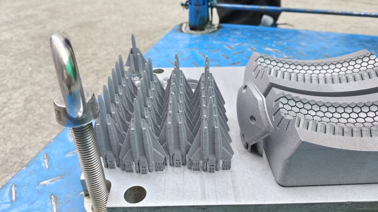
Where printed parts actually go wrong
Most failures are decided at the design desk and the quoting sheet, not on the machine.
Sending a CNC design straight to a printer
The most common mistake is a model built for milling or casting that gets exported to a printer unchanged. Every additive process carries its own constraints: minimum overhang angle, support strategy, powder evacuation paths, and build orientation. Skip those rules and you get sagging 45° bridges, rough down-facing surfaces, and internal channels packed with support that nobody can remove.
A customer once sent an impeller with cooling channels oriented vertically for a titanium powder-bed build. Powder stayed trapped inside and the supports could not be reached. Three failed builds later, the project was late and over budget.
Design for the process, not around it. And ask a harder question first: does this geometry actually benefit from additive? A compact part that needs high structural integrity is usually safer machined from solid stock. Five-axis CNC reaches internal channels from the side, and there is no support material to remove at all.
Choosing material by trade name instead of data sheet
Teams often pick a printed material because the name sounds close to something they already run. They ask for stainless steel without saying 316L or 17-4PH. They request aluminum without realizing the printed alloy is AlSi10Mg, not 6061-T6. Those are not interchangeable, and the difference shows up in yield strength, elongation, and corrosion behavior.
The deeper issue is anisotropy. Powder-bed fusion parts, whether SLM or DMLS, have a layered microstructure. Tensile properties along the build direction differ from properties across it. A test coupon cut one way may pass while the same material fails in the part.
For structural work such as aerospace brackets, automotive mounts, or robot joints, that directional dependence is a real liability. Orient the part to pack the build plate rather than to align with the load path, and failure can start well below the design stress. Wrought 6061-T6 or 17-4PH machined from bar has uniform properties in every direction.
Expecting machining tolerances from a printer
A printer does not hold the same numbers as a mill. As-built metal powder-bed parts typically land around ±0.1 mm on well-controlled features and worse on overhangs, thin walls, and long spans. Layer thickness sets a floor on surface finish, and down-facing surfaces are rougher than up-facing ones.
Then the part moves. Residual stress from rapid heating and cooling can warp a thin plate or bow a long bracket after it is cut from the build plate. Annealing helps, but it adds a furnace cycle and a second setup.
If a drawing calls for ±0.005 mm on a bore, a flatness callout, or Ra 0.8–1.6 μm on a sealing face, printing will not get there in one step. The usual route is print, then machine the critical features. That works, but budget the extra setup, the extra fixture, and the extra days. On many parts the hybrid route costs more than cutting the whole part from bar.
Additive or subtractive: a quick check
Use this as a first filter before you commit to a process route.
| Condition | Printed part | CNC machined part |
|---|---|---|
| Internal channels or lattice | Strong fit, supports removable | Hard to reach, needs split design |
| Tolerance tighter than ±0.05 mm | Needs secondary machining | Holds ±0.005 mm as machined |
| Load direction known | Anisotropy must be managed | Isotropic from wrought stock |
| Quantity above a few hundred | Build time scales with parts | Cycle time drops per part |
| One-off with simple geometry | Fast, no tooling, light cleanup | Fast on 5-axis, no tooling |
| Large monolithic frame | Build envelope limits size | Up to 4,000 mm processing size |
Post-processing time and cost per part
Post-processing is where printed-part quotes go wrong. Support removal on a metal build can take hours by hand. Stress relief, HIP, and heat treat add furnace cycles. Then comes depowdering, tumbling, bead blasting, and any machining of critical faces. Each step is a touch, and each touch is labor.
Surface finish expectations make this worse. A printed surface at Ra 8–12 μm needs a lot of work to reach Ra 0.8–1.6 μm. On a machined part, that finish comes off the tool in one pass.
Cost per part is the second trap. Printing is competitive at low volume because there is no tooling. It stops being competitive when the same part is needed in the hundreds, because build time scales roughly with part count while CNC cycle time falls with better fixturing and multi-part setups. Run the numbers at 1, 50, and 500 pieces before you commit. The crossover is usually earlier than teams expect.
Quality evidence and the geometry myth
Regulated industries need more than a good-looking part. Aerospace, automotive, and medical buyers ask for material certificates, process records, and traceability back to the powder lot or the heat number. If your supplier cannot provide that, the part may pass inspection and still fail the audit.
Printing also carries hidden defects. Porosity, lack of fusion, and unmelted powder can sit below the surface and be invisible. X-ray CT or destructive sectioning is the way to find them, and both cost money and time. Machined parts have their own risks, but a 100% inspection routine with dimensional reports covers most of them.
The last mistake is believing a printer can build any geometry. It cannot. Overhangs below about 45° need support. Enclosed channels need an escape path. Thin walls have a minimum thickness. Large flat plates warp. Know the limits before you promise a shape to a customer.
Questions engineers ask next
Can I print a part and then machine only the critical features?
Yes, and it is a common hybrid route. Print the blank with stock on the faces that need tight tolerance, then set it up on a mill and cut those features.
Budget for the extra setup and fixture. The printed blank must have enough stock for the machining pass, and its as-built distortion has to be measured first.
How do I deal with anisotropy in a load-bearing printed part?
Align the build direction with the dominant load path where you can, and document that orientation on the drawing.
For safety-critical parts, test coupons built in the same orientation rather than relying on the data sheet alone. If the load path changes direction inside the part, wrought metal is the simpler answer.
What tolerance should I expect from as-built metal printing?
Plan on roughly ±0.1 mm on well-controlled features, and looser on overhangs, thin walls, and long spans. Surface finish is limited by layer thickness.
Tolerances of ±0.005 mm and finishes of Ra 0.2–0.8 μm come from machining, not from the printer.
At what quantity does CNC machining become cheaper than printing?
It depends on geometry, but the crossover often lands in the tens to low hundreds. Printing has no tooling cost, so it wins on one-offs with complex internal features.
Once a part needs secondary machining on top of printing, subtractive usually wins earlier. Get both routes quoted at the same quantity before deciding.
What quality documents can a machining supplier provide?
Material certificates, dimensional inspection reports, and process records are standard on request. GreatLight holds ISO 9001:2015, IATF 16949:2016, ISO 13485:2016, and ISO 27001:2022.
Inspection covers raw material check, in-process monitoring, and final inspection, with 100% inspection before shipment.
Which geometries really need additive manufacturing?
Parts with internal conformal cooling channels, lattice structures, or organic ribs that cannot be reached by a cutter benefit most.
If the part is compact, has simple external features, and needs tight tolerance or high structural integrity, machining from solid stock is usually more reliable.
Send the drawing, get both routes compared
We review your model, tell you whether printing or 5-axis CNC fits, and quote it with a free DFM analysis.
12-hour quote and DFM100% inspection before shipment±0.005 mm tolerance









