
Tour and Milling Machine: What Actually Changes on a CNC Machine
Both processes remove metal with a spinning tool or a spinning part. The difference is what rotates and which features you can hold. This page is for engineers and buyers who need to pick a process from a drawing, not a textbook.
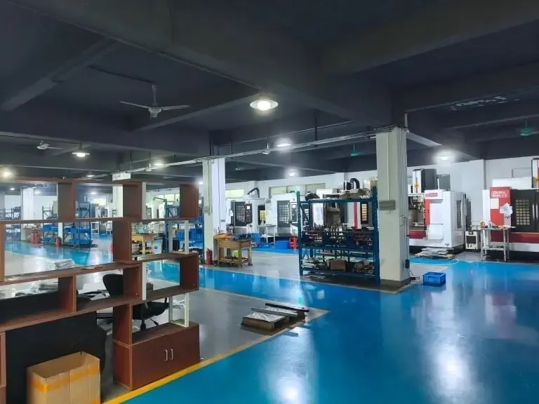
Tour and milling machine at a glance
Figures are typical ranges for our shop, not universal limits.
| Point | Turning (lathe) | Milling (mill) |
|---|---|---|
| What rotates | The workpiece spins | The cutter spins |
| Part geometry | Round or near-round bodies | Prismatic, pockets, faces |
| Typical start stock | Bar or cast round blank | Plate, block or casting |
| Main features | Diameters, bores, threads, grooves | Slots, steps, profiles, holes |
| Hole axis | On the centerline | Any direction, any face |
| Best form tolerance | Roundness, concentricity | Flatness, squareness, position |
| One-setup output | High for round parts | High for boxy parts |
| Weak spot | Off-axis holes, flats, slots | Large round diameters, thin walls |
| Shop tolerance | ±0.005 mm on critical dims | ±0.005 mm on critical dims |
What actually rotates, and why it decides the part
On a lathe the workpiece turns and a single-point tool feeds along X and Z. On a mill the workpiece stays clamped and the spindle turns a multi-tooth cutter that moves in X, Y and Z. That one difference decides almost everything downstream: which features are cheap, which need a second setup, and where the tolerance error comes from.
On a tour and milling machine comparison, the roundness of a turned part comes from the spindle bearing and the slide, not from the tool profile. That is why turning holds roundness and concentricity well. A mill makes roundness from a circular interpolation path, so the result depends on servo tuning and cutter runout.
Milling cuts with an interrupted edge. Each insert or flute enters and exits the material, so the load on the tool changes many times per second. Turning with a single-point tool keeps a more constant load. This is why milling tends to chatter sooner on thin walls, and why turning handles long slender shafts better.
Neither process is more accurate in the abstract. A mill can face a plate flat to 0.02 mm over 500 mm. A lathe can hold a Ø50 mm journal to ±0.005 mm. Put the same feature on the wrong machine and both numbers fall apart.
- 1Rotation defines the axisTurning works around one centerline. Milling works on any face you can reach.
- 2Tool contact differsSingle-point turning gives steady load; milling gives interrupted load.
- 3Error sources differTurning error comes from spindle and slides; milling error from toolpath and runout.
Features that decide the process: diameters, flats and holes
Start with the feature list, not the part name. Diameters, bores, threads, grooves, chamfers and face grooves all sit on a common axis, so a lathe owns them. Slots, keyways, pockets, steps, angled faces and holes that do not run through the centerline belong to a mill.
A shaft with a keyway is the classic mixed case. Turn the Ø, then mill the keyway. Two setups, two datums, and the position of the keyway relative to the diameter now depends on how well the second setup repeats. A mill-turn center does both in one clamping, which removes that stack-up.
A housing with a big bore and a bolt circle is the mirror image. The bore is a turning feature. The bolt circle is a milling feature. If the drawing calls the bolt circle position from the bore centerline, doing both in one setup is the cleanest route.
When the feature count is mostly round, stay on a lathe. When it is mostly prismatic, stay on a mill. When it is roughly half and half, price both one-setup mill-turn and two-setup turning plus milling before you commit.
- 1Lathe-ownedDiameters, bores, threads, grooves, chamfers, face grooves.
- 2Mill-ownedSlots, pockets, keyways, steps, off-axis holes, angled faces.
- 3Mixed casesShaft with keyway, housing with bolt circle. Check the datum chain.
- 4Rule of thumbMostly round goes to turning; mostly prismatic goes to milling.
Tolerances, surface finish and where each process struggles
For critical dimensions we work to ±0.005 mm. Surface finish ranges from Ra 0.2–0.8 μm on fine work to Ra 1.6–3.2 μm as machined. Those numbers are achievable on either process, but not on every geometry. A long boring bar on a lathe will deflect and pull the bore off size. A long end mill on a mill will deflect and leave taper on a wall.
Reach ratio is the practical limit. In turning, a boring bar at 4:1 length-to-diameter is comfortable; past 6:1 you should expect to slow down and take lighter passes. In milling, a cutter at 3:1 in aluminium is normal; at 8:1 the wall will sing unless you reduce radial engagement.
Thin walls punish milling more than turning. A Ø80 mm tube with a 2 mm wall turns well because the load is steady and radial. Mill a flat on that same tube and the wall deflects away from the cutter, so the flat comes out thin in the middle. Support it with a fixture or turn it instead.
Hard materials shift the balance. Inconel and Ti-6Al-4V cut better on a rigid five-axis mill with coolant through the spindle than on a small lathe, but a simple turned bushing in 17-4PH is still lathe work. Match the machine to the material and the feature, not to the alloy name.
- 1Reach limitsBoring bar fine to 4:1; long end mills need reduced engagement.
- 2Thin wallsTurning handles tubes; milling flattens them unless supported.
- 3Hard alloysRigid five-axis mill for Inconel and Ti-6Al-4V pockets.
How we choose on the floor, and how to read a quote
We look at the drawing in this order: feature list, datum scheme, batch size, material. Features tell us the primary process. Datums tell us how many setups. Batch size tells us whether a fixture or a bar feeder pays off. Material tells us about tool life and coolant.
A one-off prototype often goes on a five-axis mill even when it is round, because one setup beats two. A 5,000-piece run of the same round part goes on a lathe with bar feed, because cycle time dominates. The same drawing can justify opposite choices.
Our shop runs 127 high-precision CNC machines, including 16 simultaneous 5-axis centers, 12 four-axis mills, 27 three-axis machines and 16 mill-turn centers. Maximum processing size is 4,000 mm. That mix matters when a part needs turning, milling and drilling without losing the datum.
Every part is inspected 100% before shipment, with raw material check, in-process monitoring and final inspection. Reports are available on request. If your drawing has a tolerance you are unsure about, send it with the model and we will flag it during DFM review.
- 1Read the drawing in orderFeatures, datums, batch size, material.
- 2Batch size flips the answerOne-offs favor one-setup milling; high volume favors bar-fed turning.
- 3Ask for DFMQuotation and free DFM analysis within 12 hours.
Which one to pick
If the part is mostly round with features on one centerline, choose turning. If it is prismatic, or the critical features sit off-axis, choose milling. If it is half and half, price a mill-turn center in one setup before you accept a two-setup route.
Common questions
Can a milling machine do turning work?
A mill can turn a diameter with a rotary table or a lathe tool in the spindle, but it is slow and the roundness depends on interpolation. For anything beyond a short cleanup cut, a lathe or mill-turn center is the better route.
Is turning cheaper than milling?
For round parts in volume, turning usually costs less per piece because cycle time is short and bar feed removes loading time. For one-off prismatic parts, milling wins because it needs fewer setups. Price depends on features and batch size, not on the process name.
What is a mill-turn center used for?
It turns and mills in one clamping. It suits parts with a round body plus off-axis holes, flats or slots where the position of those features is called from the turned centerline. Our shop runs 16 mill-turn centers.
Which process holds tighter tolerance?
Both reach ±0.005 mm on critical dimensions when the setup is rigid. Turning holds roundness and concentricity better. Milling holds flatness, squareness and hole position better. Match the process to the tolerance that matters on your drawing.
How do I decide for a prototype?
For a single part, count the setups. A five-axis mill can often finish a complex part in one clamping, which beats two setups on a lathe even for round parts. Send the model and we will return a DFM note with the recommended route within 12 hours.
Send the drawing, get a route back
Upload your model and we will tell you which process fits, with a quotation and DFM analysis within 12 hours.
12-hour quote100% inspectionNo minimum order quantityNDA on request
More from the shop floor
We publish setup notes, tooling trials and inspection data from the factory floor.











