
What Is Nesting in CNC Machines?
Nesting in CNC machines is the arrangement of part profiles on a sheet, plate or block so that material, cutting time and fixturing all pull in the same direction. This page explains the two nesting families, the constraints that decide the layout, and when nesting stops paying for itself.
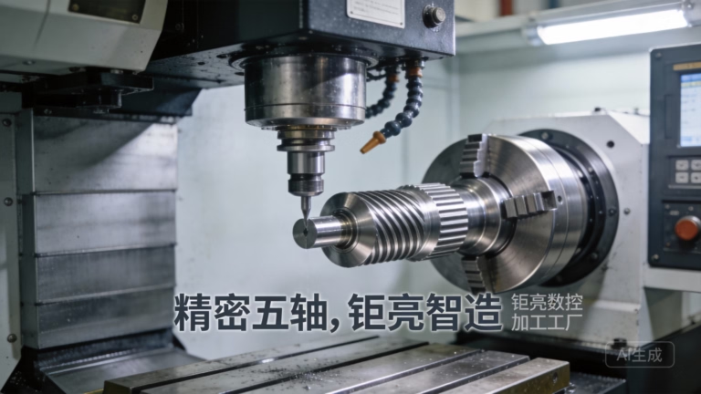
How nesting in CNC machines actually works
Nesting is a layout problem before it is a machining problem. You have a fixed raw stock size: a 1,220 × 2,440 mm sheet, a 4,000 mm plate, or a rectangular block. You have a list of part outlines with their own sizes and quantities. The job is to place every outline inside the stock boundary without overlap.
For 2D work the parts are flat profiles, cut on a laser, waterjet, plasma table, router or punch. For 3D work the parts are solid geometries cut from plate or block on a mill, usually a 3-axis or 5-axis machine. Both cases run the same arithmetic: total part area or volume divided by stock area or volume. That ratio is the material yield.
The gap between yield and 100% is where cost lives. A sheet that yields 78% leaves 22% as scrap or remnant. On aluminium plate the material line often runs 30–50% of the part price, so a ten-point yield gain is not a rounding error. It changes what you pay.
Software does the search, but the search is bounded by real machine limits. A nesting routine that ignores the tool envelope produces a beautiful layout that cannot be cut. The useful engines treat machine constraints as hard inputs, not as warnings to fix later.
Sheet and plate nesting: geometry, kerf and grain
Sheet nesting packs profiles into a flat boundary. The packing rules are geometric. Parts can be rotated, mirrored, or moved to a common edge. Two profiles can share a cut line only if the process allows it; laser and waterjet usually do not, because the kerf removes material on both sides.
Kerf is the width of material destroyed by the cut. A typical fibre laser kerf sits between 0.1 mm and 0.5 mm depending on thickness and lens. If you are cutting 400 small brackets, that lost strip adds up. Nesting software compensates by spacing parts at the kerf width plus a safety margin, often 0.5 mm to 2 mm.
Grain direction is a hard constraint in some materials. Anisotropic sheet such as rolled aluminium or carbon fibre laminate has different strength along and across the rolling direction. If a part sees bending load, the engineer may specify grain orientation, which removes the rotate-freely option for that profile.
Edge quality also constrains spacing. A part that will be welded needs a clean edge, so it is placed away from the sheet border where dross and pierce spatter are more likely. A part that will be machined after cutting can sit closer to the edge, because the rough cut is not the final surface.
Block and plate nesting for milled parts
In 3D nesting, the stock is a block or a thick plate, and the part is removed from it by milling. The layout question becomes: how many part geometries fit inside one block volume, and where do you place the work offsets so each part can be reached by the tool?
The dominant loss in block machining is not the chip. It is the leftover skeleton. When you cut three parts from one block, the webs between them and the base plate remain as scrap unless the layout was designed so the block can be re-used for a smaller job. This is where a nesting decision today becomes a remnant decision tomorrow.
Clamping is the second constraint. A vise jaw needs flat, parallel surfaces. A 5-axis setup may need a dovetail or a fixture boss that gets cut off later. Those features consume stock volume that nesting must reserve. A layout that ignores workholding will fail at the machine, not in the software.
Tool reach is the third. A deep pocket needs a long tool, and a long tool needs clearance around the part. If two parts sit 30 mm apart, the tool holder may collide with the neighbour. Spacing in 3D nesting is driven by the holder envelope, not by the part outline.
When nesting helps and when it does not
High part count is the clearest signal. Twenty or two hundred small brackets, washers, covers or gaskets on one sheet is exactly the case nesting was built for. The saving scales with quantity, so a 10,000-part run can justify a layout study on its own.
Mixed part families are the second signal. When one order contains several different small parts, manual layout becomes slow and error-prone. Automatic nesting searches combinations a person would not try, and it does not get tired at part 60.
Nesting pays less when the part is large relative to the stock. If one part occupies 80% of a sheet, there is little left to optimise. The layout is essentially fixed, and the remaining work is about edge margin and cut sequencing, not about packing.
It also pays less when the part needs a lot of machining after cutting. If the blank is only a starting shape and 6 mm will be removed from every face, the exact profile of the blank matters less. The nesting gain gets absorbed by the machining allowance.
2D sheet nesting vs 3D block nesting
Match the layout method to the process and the stock form.
| Factor | 2D sheet nesting | 3D block nesting |
|---|---|---|
| Typical process | Laser, waterjet, plasma, punch, router | 3-axis and 5-axis milling from plate or block |
| Stock form | Sheet or thin plate | Plate, bar or solid block |
| Main loss | Scrap skeleton between profiles | Remnant block and webs between parts |
| Spacing driver | Kerf width plus safety margin | Tool holder and clamp envelope |
| Hard constraint | Grain direction, edge quality | Workholding and tool reach |
| Best fit | Many small flat parts | Several parts from one thick block |
| Poor fit | One part filling most of the sheet | Part needing heavy post-cut machining |
The short answer
If your parts are flat and count in the dozens, choose 2D sheet nesting, because kerf and grain drive the layout. If your parts come out of thick plate or block on a mill, choose 3D block nesting, because workholding and tool reach decide what is possible.
Nesting questions engineers ask
Does nesting change the tolerance of my part?
No. Nesting decides where the blank sits on the stock, not how the final surface is produced. The tolerance still comes from the cutting or milling operation.
If you need ±0.005 mm, that comes from a controlled finishing pass after the rough shape is cut, not from the layout.
What material yield should I expect from nesting?
It depends on part shape and count. Irregular profiles with curves and holes leave more waste than rectangles.
More parts per sheet usually raises yield, because small parts can fill the gaps between large ones. We check the layout as part of the DFM review.
Can nesting cause parts to move during cutting?
Yes, if the layout leaves a weak skeleton. A part held only by a thin web can shift as the cut releases stress in the sheet.
The fix is to leave tabs or to sequence the cut so the part stays attached until the last pass.
Is nesting only for sheet metal?
No. The term is used for any layout that packs multiple parts into one piece of stock, including block machining on a mill.
The constraints differ, but the goal is the same: less leftover material and fewer setups.
Do I need to provide a nested layout with my drawing?
No. Send the part drawing and the quantity. We handle the layout and the cut sequence.
If grain direction or a specific blank orientation matters to your design, say so on the drawing and we will treat it as a fixed constraint.
How does nesting affect lead time?
A denser layout means fewer sheets to cut, which means less machine time per batch. That usually helps the schedule.
It does not shorten the process steps themselves. Cutting, machining, finishing and 100% inspection still run in sequence.
Send your drawing, get a layout-aware quote
We review the part geometry and the quantities, then quote with the nesting layout already considered. Quotation and free DFM analysis within 12 hours.
12-hour quote100% inspection
More machining notes
We publish setup notes, tooling trials and inspection data from the factory floor.











