
What Is Cyclonic Milling? A Clear Look at the Mechanics
Cyclonic milling, also called whirl milling, cuts with a small tool on a fast circular path instead of a large slow one. This page explains the geometry, the heat and chip behavior behind it, the parts it suits, and the cases where it costs you more than it saves. It is written for engineers and buyers who need to judge whether the process fits a real job.
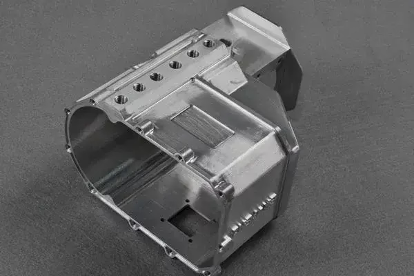
How Cyclonic Milling Actually Cuts
Cyclonic milling is a milling strategy, not a machine type. A small-diameter cutter travels around the inside of a bore or thread on a circular path while the tool also spins on its own axis. The orbit radius sets the finished diameter; the tool diameter is much smaller than the hole. Because the cutter is small, the travel speed at the cutting edge can stay high on a normal spindle.
The geometry has a useful side effect. On an internal thread, the tool engages over a long arc instead of a short one. Each edge takes many shallow bites per revolution, so chip load per tooth drops and the load is spread out. You get shorter chips and fewer chatter marks. Heat leaves with the chip instead of soaking into the part.
Contact time per tooth is longer than in a standard end mill pass. That sounds like more wear, but the chip is thin and the arc is smooth, so edge temperature stays steadier. On hardened steel above 45 HRC, this is often the difference between a stable cut and a broken tool.
The orbit is controlled by the machine, not by the tool. A 5-axis center or a mill-turn machine with live tooling can drive the path directly. On a 3-axis mill you need a helical interpolation cycle and enough Z travel to cover the thread depth. The controller does the math; your job is to give it the right pitch, diameter and feed.
- 1Small tool, large orbitThe orbit defines the bore; the cutter is typically 50-70% of the thread minor diameter.
- 2Long arc engagementLoad spreads over many teeth, so each insert sees a light chip.
- 3Chip carries the heatThin, short chips pull heat away from the workpiece.
What Is Cyclonic Milling Used For in Real Shops
The classic use is an internal thread in a part you cannot rotate. Large housings, valve bodies, mold bases and engine blocks often have threads on a bore axis that is awkward for a tap. Whirl milling cuts those threads with the part clamped once, so you keep the bore and the thread concentric.
It also suits threads near a shoulder or at the bottom of a blind hole. A tap needs run-out space and a relief groove. A whirling cutter needs only a small clearance at the top of the hole, which lets you place the thread closer to a wall or a boss. Designers use this to shrink envelope size.
Hard and gummy materials are the second big group. Inconel, 17-4PH stainless, titanium TC4 and tool steel above 45 HRC all punish taps. Whirl milling uses a smaller radial depth and a smoother entry, so torque stays low. On titanium the low cutting speed and steady chip load reduce the smearing that ruins thread flanks.
The same motion works for internal grooves, O-ring seats, spherical seats and tapered bores. Any feature that is a circle swept along an axis can be generated by an orbiting cutter. That is why the process shows up in hydraulic manifolds and aerospace housings where several of those features sit on one axis.
- 1Good fitThreads in large or non-rotating parts, hard alloys, threads close to a shoulder.
- 2Poor fitTiny threads under M4, very deep holes with weak tooling, low-cost high-volume parts.
Cyclonic Milling vs Tapping vs Thread Milling
Tapping is fast and cheap on a through hole in aluminium. The tap cuts the full profile in one pass and the cycle time is short. The catch is that the tap is as long as the thread and as rigid as its smallest section. Break one in a blind hole and the part may be scrap.
Single-point thread milling uses one insert on a helical path. It is more forgiving than tapping and works on large diameters where no tap exists. But the tool still contacts a short arc, so the chip is thicker and the load is higher. Surface finish on hard steel is usually coarser.
Cyclonic milling spreads the cut over a longer arc with a smaller tool. Finish is finer because the peaks left by each tooth are shorter and there are fewer of them. Whirling also cuts the thread in one continuous orbit rather than many passes, which helps on deep threads.
The trade-off is programming and tool cost. Whirl tools are specialized and the cycle needs correct pitch, orbit and lead-in. For a hundred M6 holes in aluminium, tap them. For an M30 thread in 17-4PH on a welded housing, whirl milling wins on risk and finish.
Accuracy, Finish and Where the Limits Sit
Thread profile accuracy depends on the orbit radius and the tool geometry. On our machines we hold ±0.005 mm on critical diameters and Ra 0.8-1.6 μm on thread flanks in stainless and titanium. A finer Ra 0.2-0.8 μm is possible on sealing faces when the setup is rigid and the tool is fresh.
Pitch error is the usual failure mode. It comes from orbit radius error, tool runout or a wrong lead value in the cycle. Check the first part with a thread gauge and a optical comparator before you run the batch. If the gauge enters two turns and binds, the pitch is off, not the diameter.
Depth is the second limit. Whirl tools are short and stiff, but a thread deeper than about 2.5 times its diameter still needs a long reach. Below M6 the orbit gets small, chip clearance gets tight, and the process loses its edge over tapping. That is the practical floor for most shops.
Wall thickness matters too. Because the load is spread, thin walls resist deformation better than with a tap. But the orbiting tool still pushes radially. If the wall is under 1.5 mm, support it or expect the bore to spring. Plan a finishing pass at low radial depth to bring it back.
- 1Hold ±0.005 mmOn critical diameters, with in-process checks on the first part.
- 2Ra 0.8-1.6 μmTypical on stainless and titanium thread flanks.
- 3M6 floorBelow this, tapping is usually the better call.
- 4Deep threadsPast 2.5 × diameter, reach and chip evacuation get hard.
Setup Rules We Use on the Floor
Rigidity first. The toolholder, the fixture and the part all sit in the same loop, and any soft point shows up as chatter on the flank. We indicate the tool to under 0.01 mm runout and check the fixture bolts before the first cut. On hard steel a loose clamp is louder than any parameter error.
Coolant should reach the cutting arc, not just the top of the hole. Through-spindle coolant or a directed nozzle works best. On titanium and Inconel, high-pressure coolant also breaks the chip and keeps the edge cool. Flood coolant alone often leaves chips packed in the thread root.
Start conservative. Take a light radial depth and the feed the tool maker lists, then raise speed until the chip color and sound settle. On 17-4PH we often start near 40-60 m/min surface speed and adjust from there. Record what worked; the next job in the same alloy will run faster.
Inspect the first part fully. We check thread gauge fit, pitch, flank finish and roundness before releasing the run. That first-part check catches orbit and tool errors while the fix is still cheap. Every part then gets 100% inspection before shipment, with reports on request.
- 1Indicate under 0.01 mmTool runout is the main source of pitch and finish error.
- 2Coolant at the arcThrough-spindle or directed nozzles beat flood coolant.
- 3First-part checkGauge, pitch and finish before the batch is released.
Choosing a Threading Method
Match the method to diameter, material and batch size.
| Method | Best for | Watch out for |
|---|---|---|
| Tapping | Small threads, soft metal, high volume | Tool breakage in blind holes |
| Single-point thread milling | Large diameters, one tool many pitches | Coarser finish on hard steel |
| Cyclonic milling | Hard alloys, threads near shoulders | Higher programming effort |
| Whirl milling on 5-axis | Complex housings, one setup | Needs 5-axis or mill-turn capacity |
| Thread rolling | Ductile metal, strong threads | No internal threads in hard steel |
When to Choose Cyclonic Milling
Choose cyclonic milling for hard alloys, large internal threads, and threads close to a shoulder or at the bottom of a blind hole. Stay with tapping for small threads under M6, soft metal, and high-volume simple parts.
Cyclonic Milling Questions
Is cyclonic milling the same as whirl milling?
Yes. Both names describe the same orbiting-cutter strategy for internal threads and circular features. Whirl milling is the more common term in thread production; cyclonic milling shows up more in general machining literature.
The motion is the same either way: a small cutter follows a circular path inside a bore while spinning on its own axis.
Can cyclonic milling replace grinding for a fine finish?
Not for every job, but the flank finish can come close on internal threads. The long arc contact leaves shorter peaks, so the surface reads smoother than a tapped thread.
Where a ground finish is specified by drawing, keep grinding. Cyclonic milling is a cutting process and still leaves a directional pattern.
What materials give the biggest gain?
Hard and gummy alloys. Inconel, 17-4PH, titanium TC4 and tool steel above 45 HRC all break taps and wear single-point tools quickly.
In aluminium and mild steel the gain is smaller. Tapping is usually faster and cheaper there.
Does it need a 5-axis machine?
No. A 3-axis mill with helical interpolation can whirl a thread if the Z travel covers the depth. A mill-turn center with live tooling also works well.
A 5-axis center helps when the thread axis is not normal to the table, or when several features sit on one angled axis and you want one setup.
What thread sizes make sense?
Roughly M6 and up on internal threads. Below that the orbit is small, chip clearance is tight, and tapping is the better choice.
There is no hard upper limit. Large housings and rings with threads over Ø300 mm are common whirl milling work.
How do you check the thread?
Thread gauges for fit, an optical comparator or thread analyzer for pitch and profile, and a surface tester for flank finish.
We check the first part fully, then run 100% inspection before shipment. Inspection reports are available on request.
Send Us Your Threaded Part
Tell us the material, thread size and hole depth. We will confirm whether cyclonic milling fits and quote within 12 hours, with a free DFM analysis.
12-hour quote100% inspectionNo minimum order
More CNC Knowledge
We publish setup notes, tooling trials and inspection data from the factory floor.











