
What Depends on the Formation of a Milling Area
The surface you get off a milling cutter is not random. It comes from the shape of the cutting edge, the feed per revolution, the runout of the holder, and the way the tool path overlaps. This page explains the mechanics of milling area formation for engineers who need to choose a tool and set parameters instead of guessing. Read it and you can tell which factor is spoiling your finish.
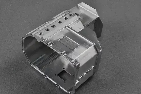
How a milling area formation Is Made
Every milled surface is a record of the tool edge moving through metal. A milling cutter does not slice a smooth plane. Each tooth leaves an arc, and the arcs overlap along the feed direction. The envelope of all those arcs is the milling area. Its shape and roughness follow from the cutter geometry and the feed, not from the spindle speed alone.
The cutter edge that touches the finished surface matters most. On a shoulder mill, the peripheral edge forms a radial surface. On a face mill, the corner or wiper edge forms an axial surface. If the tool has a wiper flat, that flat becomes the final surface and the other edges only remove stock.
Feed per revolution (fn) sets how far the tool advances during one full turn. Feed per tooth (fz) multiplied by the number of teeth gives fn. When fn is small relative to the wiper flat width, the flat can wipe the scallops left by the previous tooth. When fn grows past that flat, the scallops stay visible.
Runout changes everything. If one tooth sits 0.01 mm higher than the rest, that tooth cuts the deepest mark and the others do not touch the finish. The surface then shows the pitch of one tooth, not the pitch of the whole cutter.
Axial, Radial and Complex Surfaces
The type of surface depends on which part of the cutter does the work. An axial surface is generated by the bottom of the tool, so it is common in face milling and in the floor of a pocket. A radial surface is generated by the side of the tool, so it appears on walls and shoulders. Complex surfaces come from ball nose or bull nose tools following a curved path.
For an axial surface, the bottom edge geometry controls the finish. A flat bottom leaves a better floor than a corner radius with a large arc. The arc radius (re) imprints its own curvature onto the floor, and that curvature can show as a series of scallops between passes.
For a radial surface, the side edge and the helix angle control the finish. A positive helix shears the chip and often leaves a cleaner wall. A straight flute can chatter on thin walls because the cutting force changes sharply at entry and exit.
Complex surfaces combine both. The stepover, the tool nose radius, and the tilt of a 5-axis head all shape the final surface. A ball nose cutter with a small stepover leaves a fine finish but takes longer. A larger stepover is faster and leaves visible scallops.
Feed per Revolution and the 80 Percent Rule
The classic rule for a wiper or finishing insert is simple. Keep feed per revolution below 80 percent of the wiper flat width (BS). If fn stays under that limit, the flat can iron out the marks left by the preceding tooth. If fn goes above it, each tooth leaves its own cusp and the surface turns rough.
Feed per revolution also grows with cutter diameter. A large face mill carries more teeth, and each tooth takes its own feed. To keep fn inside the flat, you either reduce feed per tooth or reduce the number of effective teeth. Many shops run a fine finishing pass with only a few inserts engaged for this reason.
Spindle speed and feed must move together. Raising rpm without raising feed thins the chip and can rub instead of cut. Lowering feed without lowering rpm thickens the chip and can overload the edge. The cutting speed and the chip load are a pair.
Depth of cut is a separate lever. A light finishing pass of 0.2–0.5 mm axial depth keeps radial force low and holds the finish. A heavy pass pushes the cutter, and any deflection shows up as a taper or a wave on the wall.
Runout, Tool Holders and Machine Condition
Runout is often the hidden cause of a bad finish. A holder with 0.02 mm runout forces one tooth to do most of the cutting. That tooth wears fast and leaves a mark at every revolution. A hydraulic or shrink-fit holder can hold runout under 0.005 mm and change the finish on the same cutter.
Tool overhang amplifies runout. A cutter hanging 80 mm out of a holder deflects more than the same cutter hanging 40 mm out. For finishing walls, keep overhang as short as the part allows. If the part is deep, use a smaller cutter or a long-reach holder with a stiffer body.
Spindle condition matters on older machines. Bearing play shows as a repeating pattern with the frequency of the spindle, not the tooth. This is easy to misread as a feed problem. Check runout at the tool tip and at the holder taper before you change cutting data.
Thermal growth also shifts the cut. A spindle that warms up over an hour can move the tool by several microns on a long part. On tight work, warm up the machine and check the first article against a known feature.
Which Factor Controls Which Surface
Match the surface you need to the parameter that drives it.
| Surface type | Main driver | Typical setting | When it fails |
|---|---|---|---|
| Axial (floor) | Wiper flat width | fn under 80 percent of flat | fn exceeds flat, cusps appear |
| Radial (wall) | Side edge and helix | Light depth, 0.2–0.5 mm | High radial force, chatter |
| Complex (3D) | Stepover and nose radius | Stepover under 10 percent of Ø | Large stepover, visible scallops |
| Fine finish | Runout and holder | Under 0.005 mm runout | Worn holder, one tooth cuts |
| High output | Feed per tooth | Higher fz, more teeth | Finish drops, tool wear rises |
The Trade-Off You Have to Pick
If you need a fine finish, control feed per revolution and runout first; if you need output, accept a rougher surface and plan a separate finishing pass. You cannot get both from one heavy cut.
Questions Engineers Ask
Why does my finish change when I only change the holder?
Runout moves from one tooth to several teeth. A holder with low runout lets all teeth share the cut, so the mark pitch changes and the surface looks cleaner.
You did not change the cutter or the feed. The geometry of the cut changed because the load moved to a different part of each edge.
Can a large face mill leave a fine finish?
Yes, if feed per revolution stays below the wiper flat width. A large cutter with many teeth needs a lower feed per tooth to hold that limit.
If you push feed per tooth up for output, the finish drops. The diameter itself is not the problem.
Why do scallops appear between passes on a 3D surface?
The stepover is too large for the nose radius. Each pass leaves a ridge, and the ridges line up as scallops.
Reduce stepover to under 10 percent of the cutter diameter, or switch to a bull nose tool with a larger corner radius.
Does spindle speed alone control surface finish?
No. Speed sets cutting speed and chip thinning, but the finish comes from feed per revolution, runout, and edge geometry.
Raising rpm without adjusting feed often makes the finish worse because the chip thins and the edge rubs.
What runout should I aim for on a finishing cutter?
Keep tool tip runout under 0.005 mm for finishing. Under 0.01 mm is workable for roughing and semi-finishing.
Measure at the tip, not at the holder, because overhang multiplies any error.
Send the Drawing, Get a Process Plan
Tell us the material, the finish you need, and the features that matter. We will come back with a quotation and a free DFM analysis within 12 hours.
12-hour quote100% inspectionNo minimum order quantity
More Machining Notes
We publish setup notes, tooling trials and inspection data from the factory floor.











