
Robot Tensioner Brackets Rapid Prototyping
A tensioner bracket holds an idler pulley in place, so belt tension stays stable and the drive stays aligned. This page explains how robot tensioner brackets rapid prototyping actually works, which geometry and tolerances matter, and when machining from billet is the wrong call. Written for design and process engineers validating a joint, actuator or arm segment.
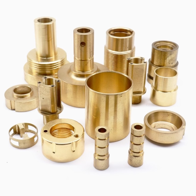
What a tensioner bracket actually does
A belt drive only behaves if the belt keeps constant preload. The tensioner bracket is the part that holds the idler pulley at a fixed offset from the driving axis. Move that offset by 0.1 mm and belt tension changes, the belt walks toward one flange, and the drive starts to whine at speed. In a collaborative arm or a mobile base, that whine becomes position error at the end effector.
Most brackets look simple in CAD. In practice they carry a bearing bore, a mounting face that registers against a gearbox or frame rail, slotted tension adjustment, and often a standoff that sets belt wrap angle. Those features live on different planes. The bracket is a tolerance stack in miniature, not a plate with holes.
The prototype has to behave like the production part. Fit, form and stiffness all matter. A bracket that is dimensionally correct but 30 percent softer in bending will change belt tension under load, and the joint you are validating will not match the joint you ship.
That is why robot tensioner brackets rapid prototyping is mostly a question of process choice. The geometry is not exotic. The behavior under load is.
Why 5-axis machining suits robot tensioner brackets rapid prototyping
The bracket has features on four or five faces: the bearing bore, the frame mounting face, the slot, and a boss that sets belt wrap. On a 3-axis mill each face needs its own setup. Every setup adds a fixture, a re-clamp, and a fresh chance for position error between the bore and the mounting face.
Simultaneous 5-axis machining cuts those faces in one setup. The bore and the mounting face come off the same zero point, so the relationship between them is set by the machine, not by how well the operator dialed in the second fixture. On a typical tensioner bracket that removes 20 to 60 μm of stack-up error before you even measure.
The second gain is access. Undercuts, angled bosses and bores that meet at an angle are normal in a tensioner. Five-axis tool orientation reaches them with a short, stiff tool instead of a long reach tool that deflects. Short tools hold size better, and they leave a cleaner floor on the bore.
The third gain is time. One setup means one queue, one fixture build, one inspection. For a single bracket that is often the difference between a two-week prototype and a four-day one.
- 1Bore-to-face relationshipSet by machine geometry, not by a second fixture.
- 2Angled bossesCut with a short tool, so size holds and finish is better.
- 3Slots and pocketsReached from the same datum as the mounting face.
Billet versus casting versus printed metal
Billet 6061-T6 or 7075 is the default for a functional bracket prototype. Properties are known, the bore takes a clean finish, and threads hold full strength. Wall thickness down to 1.5 mm is workable if you plan the fixturing. Below that, the part starts to move when you unclamp it.
Metal powder bed fusion gets you an organic shape in days, but as-built surfaces in a bearing bore are rough and the bore usually needs reaming or boring anyway. Fatigue strength is lower than wrought material unless you add a heat treat and surface step. For a bracket with a loaded bearing, that trade is rarely worth it at prototype quantity.
Die casting only pays off once tooling exists. A cast bracket has porosity, draft angles and a minimum wall that fights the stiffness you want in a tensioner. It is a production process, not a prototype process.
Bent sheet metal works for a flat L-bracket. It stops working the moment you need an integrated bearing housing, a machined face on two planes, or a bore held to ±0.005 mm. If your design has any of those, start from solid stock.
- 1Choose billet whenThe bracket carries a bearing, a thread, or a tight bore.
- 2Choose printing whenYou need form and fit only, and the bore is not critical.
- 3Avoid castingUntil annual volume justifies tooling and porosity risk.
Three failure modes that show up in prototypes
Bearing bores are the first. A reamed bore at Ra 1.6–3.2 μm can be fine for a press fit, but a slip-fit idler on a rough bore will fret and wear the housing. For a bore that sees rotation, aim for Ra 0.8–1.6 μm and hold roundness, not just diameter. A bore that measures on size but is 15 μm out of round will still let the bearing rock.
Thin walls are the second. A bracket with 2 mm walls and a wide unsupported span will distort when the vise releases. The fix is not to clamp lighter. It is to rough the part, stress-relieve or rest it, then finish in a second light cut. Material removal of 60 to 70 percent of stock in one pass is what causes the bow.
Threads are the third. Prototype brackets often need M3 or M4 threads into 3 mm of aluminum. That is about four full threads, which is workable, but only if the hole is drilled and tapped on the same setup as the mating face. Tapping in a second operation is where cross-threading and shallow threads come from.
None of these show up in a CAD review. They show up on the test stand, and by then the schedule has already slipped.
Prototyping routes for a tensioner bracket
Read the column that matches your design intent.
| Route | Bore quality | Best for | Weak point |
|---|---|---|---|
| 5-axis from billet | Ra 0.8–1.6 μm, ground if needed | Functional bracket with bearing bore | Higher unit cost at low volume |
| 3-axis from billet | Good, but setup-dependent | Flat brackets, one critical face | Multiple setups add stack-up |
| Metal 3D printing | Rough as-built, needs reaming | Form and fit checks | Lower fatigue life, porous skin |
| Die casting | Requires post-machining | Volume production only | Tooling cost, draft angles |
| Sheet metal bending | None unless welded boss added | Simple L or Z brackets | No integrated bearing housing |
Which route to pick
If the bracket holds a bearing or a precision bore, machine it from billet on 5-axis. If you only need to check packaging and fit, print it. Do not prototype a loaded bracket in cast or printed metal and expect the stiffness data to transfer.
Questions engineers ask
How tight a bore tolerance can a prototype bracket hold?
We hold ±0.005 mm on bores and mating faces on 5-axis work. That is enough for a slip-fit idler or a light press fit.
If your bearing needs a controlled interference, tell us the fit class and we will bore to the mid-point of that band rather than to nominal.
Can you match the production material in a prototype?
Yes. 6061-T6, 7075, 304 stainless, 17-4PH and Ti-6Al-4V are all available from one piece.
Matching the alloy matters more than matching the process at prototype stage, because stiffness and thread strength come from the material.
How do you stop a thin bracket from warping?
Rough the part, let it rest, then take a light finish cut. On walls under 3 mm we often leave 0.3 mm of stock for the second pass.
We also check flatness after unclamping, not just on the machine.
What surface finish should I specify on a bearing bore?
Ra 0.8–1.6 μm for a rotating or oscillating idler. Ra 1.6–3.2 μm is usually fine for a static locating bore.
Do not specify a polish unless the bore actually rotates. It adds cost and can round the edge you need for a press fit.
Can you start before the design is frozen?
Yes. We return a quotation and a DFM analysis within 12 hours, and production can start within 24 hours of that.
For a bracket with an open bore spec, we will flag the risk rather than guess.
Do you sign an NDA for robot programs?
An NDA is available on request, and uploads are kept confidential.
We work with ISO 27001:2022 information security controls, which most robotics customers ask about early.
Send the bracket, get a machinable answer
Upload the STEP file and we return a quotation with DFM notes within 12 hours. No minimum order quantity, from one prototype upward.
12-hour quote100% inspectionNDA on request
More from GreatLight
We publish setup notes, tooling trials and inspection data from the factory floor.











