

Robot Copper Bus Bars Sheet Metal Fabrication
Robot Copper Bus Bars Sheet Metal Fabrication is a specialized discipline that sits at the intersection of electrical engineering and precision manufacturing. In advanced robotics—whether for humanoid assistants, automated guided vehicles (AGVs), or industrial cobots—power distribution must be both compact and robust. Copper bus bars formed through high‑precision sheet metal processes provide the backbone of efficient, low‑resistance current delivery while withstanding vibration, thermal cycling, and tight packaging constraints. Yet sourcing these seemingly simple components often reveals a maze of technical challenges: inconsistent bending tolerances, unpredictable plating quality, and supply chains that struggle to iterate from prototype to production. In this article, we will explore why copper dominates bus bar design, how modern sheet metal fabrication meets robotic‑grade requirements, and what to look for in a manufacturing partner that can seamlessly integrate precision CNC machining with end‑to‑end fabrication.
Robot Copper Bus Bars Sheet Metal Fabrication: An Overview
Robotic systems demand a power distribution network that is lightweight, space‑efficient, and capable of handling high currents without excessive heat buildup. Bus bars—rigid copper or aluminum conductors—replace traditional wire harnesses in many applications, reducing assembly complexity and improving reliability. When produced via sheet metal fabrication, manufacturers can achieve intricate three‑dimensional shapes, precise mounting features, and surface treatments that combat oxidation and electrical corona. However, the process is far from trivial: the combination of tight mechanical tolerances and critical electrical performance makes robot copper bus bars a prime example of the need for integrated, high‑precision manufacturing.
Why Copper is the Material of Choice
Copper possesses the highest electrical conductivity among non‑precious metals, second only to silver. At 20°C, pure copper exhibits a conductivity of approximately 5.96×10⁷ S/m, giving it a distinct advantage over aluminum (3.5×10⁷ S/m) for equal cross‑sectional area. This translates into lower resistive losses, reduced voltage drop, and less heat generation—factors that are paramount in battery‑powered robots where every watt matters. Additionally, copper’s ductility allows it to be formed into complex bends without cracking, a necessity when bus bars must navigate around motors, gearboxes, and sensors in compact robotic joints.
Alloy selection further refines properties. Oxygen‑free high‑thermal‑conductivity (OFHC) copper is often specified for high‑current applications where oxidation resistance at elevated temperatures is critical. In sheet metal fabrication, copper clad laminates (C11000 or C10200) are the most common starting materials, offering an optimal balance of formability, conductivity, and cost. Selecting the right copper grade and temper is the first step in a robust bus bar design.
Sheet Metal Fabrication Techniques for Bus Bars
Producing robot‑grade copper bus bars typically involves a sequence of processes that demand both precision and repeatability:
Laser Cutting or Turret Punching – Blanking the initial profiles with tight edge conditions to ensure consistent current flow and to create the geometry for subsequent forming.
CNC Bending (Press Brake Forming) – Achieves angle accuracies within ±0.5° on modern electric press brakes, critical for bus bars that must align perfectly with multiple PCB connectors or terminal blocks.
Tapping and Thread Cutting – Adding threaded holes for fasteners without compromising current path cross‑sections.
Deburring and Edge Conditioning – Critical for both safety and electrical performance; sharp edges can be sites for arc initiation in high‑voltage systems.
Plating and Coating – Tin, nickel, or silver plating to prevent oxidation and to maintain low contact resistance at connection points.
Insulation Application – Epoxy powder coating, heat‑shrink sleeving, or insulating caps to guard against short circuits.
When these processes are performed under a single quality management system, from raw material inspection to final electrical testing, the outcome is a bus bar that meets both dimensional and electrical specifications without the need for costly re‑work.
Design Considerations for Robot‑Specific Bus Bars
Designing a copper bus bar for a robotic platform is a balancing act. Electrical and mechanical requirements often pull in opposite directions, and the constraints become tighter as robots evolve toward higher power density and lighter weight.
Electrical and Thermal Performance
The bus bar cross‑section must be sized to carry the maximum continuous current without excessive temperature rise. A rule of thumb: a 1 mm² cross‑section of pure copper can carry around 6–8 A in free air, but inside a robot’s confined housing this may drop to 3–4 A due to reduced cooling. Thermal simulation is often necessary to ensure that adjacent components are not damaged by conducted heat. High‑quality fabricators will validate current‑carrying capacity through temperature rise tests, correlating results with IEC 61439 or UL 1558 standards where applicable.
Mechanical Durability and Weight Constraints
Robots experience dynamic loads—joint acceleration, vibration, even impact. Bus bars must be stiff enough to avoid fatigue‑crack propagation, yet thin enough to minimize mass. Copper’s density (8.96 g/cm³) means that even a small reduction in thickness can shave grams from a robot’s total weight. Advanced processes like hydroforming or additive manufacturing (3D printed copper) may be considered, but sheet metal fabrication remains the most cost‑effective method for production volumes from tens to tens of thousands. Intelligent design features such as reinforcing ribs, coined corners, or selective thinning (made possible by CNC machining) allow the bus bar to maintain strength while shedding unnecessary weight.
Choosing a Manufacturing Partner: Capabilities to Look For
Procurement professionals and engineers quickly learn that not all sheet metal shops are created equal. Robot copper bus bars lie at the high‑end of the tolerance and cleanliness spectrum, demanding a partner that can offer both sheet metal expertise and advanced machining support under one roof.
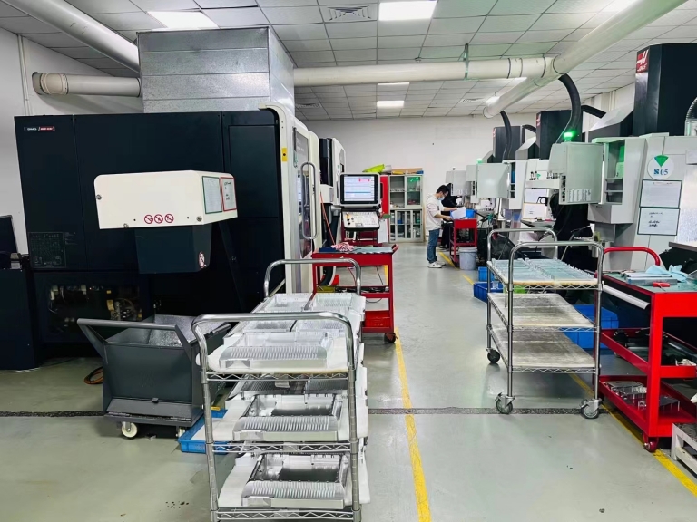
Precision Machining and Fabrication Under One Roof
Many suppliers specialize only in sheet metal forming or only in CNC milling. A bus bar, however, often requires precision‑machined interfaces—pressed‑in PEM nuts, precisely counterbored holes for flush screw heads, or even micron‑level flatness on mounting surfaces. A supplier that houses five‑axis CNC machining centers alongside sheet metal equipment can blend these operations seamlessly, reducing work‑in‑progress and qualification steps. For instance, precision CNC machining can be employed to create custom bushing inserts or to finish critical functional surfaces after forming, ensuring that pressed‑fit components do not deform under assembly torque. This integrated approach avoids tolerance stack‑up issues that plague multi‑vendor supply chains.
Quality Certifications That Build Trust
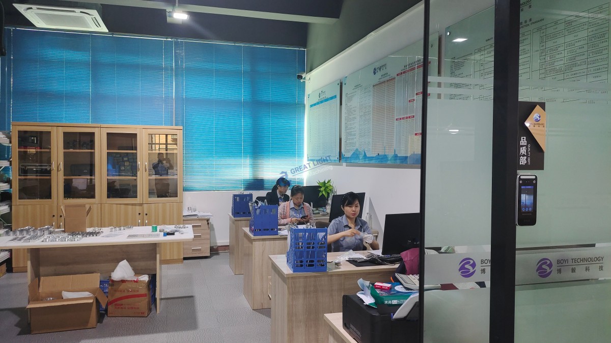
Certifications are the tangible evidence of a manufacturer’s commitment to consistency. GreatLight CNC Machining, for example, adheres to ISO 9001:2015 for general quality management, and also holds ISO 13485 for medical device‑grade traceability, IATF 16949 for automotive serial production, and ISO 27001 for data security. When a bus bar is destined for a surgical robot or an autonomous vehicle, these credentials assure that the processes are audited, repeatable, and compliant with industry regulations. Moreover, the inclusion of in‑house CMM inspection and X‑ray fluorescence (XRF) coating thickness verification guarantees that every batch of copper bus bars meets the same high bar.
Prototyping to Production Scalability
Robotics development cycles are notoriously compressed. The right manufacturing partner can accelerate the time from CAD model to functional prototype through rapid sheet metal prototyping—laser cutting and bending within days—and then scale to thousands of parts with dedicated tooling, all without changing suppliers or requalifying processes. This continuity eliminates the “iteration gap” that plagues many hardware startups and ensures that production units are identical to the approved prototype.
Competitive Landscape: How GreatLight Metal Compares to Other Providers
To help engineers evaluate their options objectively, we have compared GreatLight Metal with several other well‑known global manufacturers that offer sheet metal and CNC services for robotic components. The table below summarizes key differentiators.
| Category | GreatLight Metal | Protocase | RapidDirect | Xometry (Network) | JLCCNC |
|---|---|---|---|---|---|
| In‑House 5‑Axis CNC | Yes (Dema, Jingdiao centers) | No (primarily sheet metal & 3‑axis) | No (brokered) | No (distributed network) | Limited in‑house, mostly 3‑/4‑axis |
| Sheet Metal Thickness Range | 0.5 – 6.0 mm copper, aluminum, stainless | 0.5 – 3.0 mm (focus on enclosures) | 0.5 – 20 mm (multi‑material) | Varies by partner | 0.8 – 6.0 mm |
| Integrated Post‑Processing | Plating (Ni, Ag, Sn), anodizing, powder coating, silk screening | Powder coating, anodizing, digital printing | Outsourced post‑processing | Varies by shop | Limited in‑house plating |
| Certifications | ISO 9001, IATF 16949, ISO 13485, ISO 27001 | ISO 9001 | ISO 9001 | Varies by partner; platform has ISO 9001 | ISO 9001, IATF 16949 |
| Typical Lead Time (Prototype) | 3–7 days | 2–3 days (for simple enclosures) | 5–10 days | 5–12 days | 5–10 days |
| Complex Bus Bar Capability | High – in‑house bending + CNC + plating | Medium – mainly flat or simple bends | Medium – quality depends on sub‑contractor | Highly variable | Good for straightform, less for complex 3D |
While Protocase and JLCCNC excel at rapid enclosures and simpler bent parts, GreatLight Metal’s concurrent in‑house CNC and sheet metal capability, coupled with an extensive array of surface finishing options, positions it as a single‑source solution for robot copper bus bars that require machined features, tight tolerances, and high‑reliability plating.
Solving Common Pain Points in Custom Bus Bar Manufacturing
The information‑gap in the market often leads to surprises: bus bars that do not meet flatness spec, plating that peels after thermal cycling, or threads that strip under torque. Addressing these pain points proactively with a qualified supplier can save months of re‑design.
Precision Assurance with Advanced Metrology
Tolerance specifications such as ±0.05 mm on hole positions or 0.1 mm flatness over a 200‑mm span require more than a tape measure. Manufacturers that deploy coordinate measuring machines (CMMs) with laser scanning capabilities can provide full‑surface deviation maps, ensuring that bus bar mounting faces will mate perfectly with their counterparts. This is particularly crucial when bus bars straddle multiple connection points across a lithium‑ion battery pack. GreatLight Metal’s in‑house metrology lab, which routinely measures parts to 0.001 mm resolution, instills confidence that each batch is delivered with detailed inspection reports—no guessing, no “close‑enough” assumptions.
Integrated Post‑Processing for Electrical Insulation and Corrosion Resistance
Copper’s Achilles’ heel is oxidation. Over time, a patina forms that increases contact resistance—an unwelcome effect in low‑voltage high‑current circuits. Electroless nickel plating provides a uniform, corrosion‑resistant barrier with excellent solderability; silver plating offers the ultimate conductivity at the expense of cost. The best suppliers handle plating in‑house or through tightly controlled partners, verifying adhesion via tape tests and thickness via XRF. In addition, insulating coatings such as epoxy powder or heat shrink provide dielectric protection without adding bulk. GreatLight Metal’s one‑stop surface finishing capabilities ensure that bus bars leave the factory fully ready for installation—a significant advantage when production deadlines are tight.
A Real‑World Scenario: Bus Bar Solution for a Robotics Innovator
A recent engagement illustrates the value of an integrated manufacturing partner. A humanoid robotics company faced a critical challenge: they needed a set of copper bus bars for a joint actuator assembly that would carry 120 A continuous while fitting within a 15 mm‑wide channel. The initial designs, fabricated by a sheet metal‑only shop, suffered from burred edges that cut into insulation and inconsistent bend angles that caused misalignment during automated assembly.
GreatLight Metal’s application engineering team worked with the customer’s designers to optimize the flat pattern. They recommended a C10200 half‑hard copper to balance formability and strength, and introduced micro‑chamfers via CNC edge finishing to eliminate burrs. The bus bars were bent on a precision press brake with an angle repeatability of ±0.2°, then nickel plated and oven‑cured. A final 100% electrical resistance check verified that each bar fell within 2% of the predicted value. The result: a 35% reduction in assembly time and zero returns over six production runs. This case underscores how professional sheet metal fabrication, backed by machining expertise and rigorous quality control, transforms a high‑risk component into a reliable cornerstone of a robotic system.
Conclusion
Ultimately, the success of a robotic system may hinge on the quality of its power distribution, making Robot Copper Bus Bars Sheet Metal Fabrication a process that demands uncompromising precision, rigorous testing, and a manufacturing partner fluent in both mechanical and electrical requirements. Choosing the right precision manufacturing partner for your Robot Copper Bus Bars Sheet Metal Fabrication project can make all the difference. Precision manufacturing partner



















