
Robot Actuator Housing CNC Machining China: How These Parts Are Actually Made
An actuator housing holds the motor, gearbox, encoder and bearing bores in one rigid body. This page explains the machining mechanics behind robot actuator housing CNC machining China, where the real limits sit, and how to judge a process before you release a drawing.
In this article
- 1
- 2
- 3
- 4
- 5
- 6
- 7
- 8
What a Robot Actuator Housing Actually Has to Do
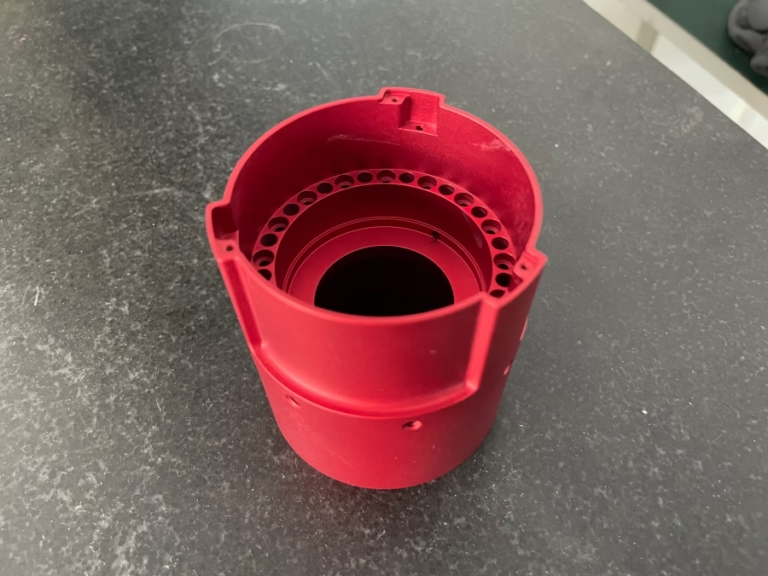
An actuator housing is a motor mount, a gearbox shell and a bearing carrier in one body. The motor stator sits in a bore at one end. The harmonic or cycloidal reducer sits at the other. Between them are bearing seats, a cable passage, sensor pockets and mounting flanges that bolt to the next link of the arm.
That stacking is why the housing is more than a cover. Every bore position sets the mesh of the gear train. If the output bearing seat sits 0.03 mm off the motor bore axis, the reducer runs with a side load it was never designed for. You hear it as noise at low speed and feel it as heat after ten minutes.
The housing also carries heat. Motor losses and gear friction both end up in the aluminum. A wall that is too thick insulates the windings; too thin and the part rings under load. Most joint housings we machine land between 2 mm and 4 mm on the main shell, with local bosses thickened where bolts and bearing seats sit.
So the drawing is really a stack of tolerances. Bore diameter, bore position, shoulder squareness and wall thickness all interact. Get one wrong and the joint still assembles, but it will not hold repeatability over a million cycles.
Why Tight Tolerances and Complex Geometry Drive the Process
The features that matter most are rarely on the same face. A motor bore on the top face, an output bore on the bottom face, and a cross shaft at 90° are typical. On a three-axis machine each face needs its own fixture, and every refixture adds error.
This is where 5-axis work changes the math. With a trunnion table the part stays clamped while the tool reaches the motor bore, the gear pocket and the mounting flange in one setup. Datum error does not accumulate the way it does across three fixtures. We hold bore-to-bore true position within ±0.005 mm on parts like this, and coaxiality between the motor and output bores is usually the number that decides whether the joint passes.
Complexity also shows up as interrupted cuts. A housing with cooling ribs, lightening pockets and cable channels gives the cutter a stop-start load. The tool deflects differently in each pass, so the finish varies around the bore. Roughing with a smaller radial engagement and finishing with a sharp, low-radius insert keeps the bore round instead of lobed.
Not every housing needs five axes. A simple cylindrical motor can with one bore and a flat flange is faster and cheaper on a three-axis mill. The rule we use: if the part has two or more critical bores that are not parallel, or if a single setup would need more than three part orientations, the setup count on three axes will cost you more in tolerance than the machine time saves.
Material Choice Sets the Machining Window
Most actuator housings are aluminum, and for good reason. 6061-T6 is the default: it machines clean, takes anodizing well and holds a bore. 7075 gives higher strength at the flange but is less forgiving on thin walls because it springs back more. 2024 sits between them and is often chosen for weight-critical arms.
When the joint runs hot or the environment is wet, stainless enters the picture. 304 and 316L are common for washdown or medical-adjacent robots; 17-4PH is used where strength and corrosion resistance both matter. Stainless moves more under cutting heat, so we slow the spindle, take lighter finishing passes and expect more in-process checks.
Titanium and magnesium appear in weight-driven designs. TC4 (Ti-6Al-4V) is strong and light but has low thermal conductivity, so heat stays at the cutting edge. Tools wear fast and the finish can smear if feed is too low. Magnesium AZ31B machines quickly but the chips are a fire risk and need dedicated handling.
Material also decides the finish. Anodizing a 6061 housing with a 2 mm wall can bow the part if the anodize thickness is uneven. Hardcoat adds more build-up than clear anodize and can close a tight bore. We plan the pre-anodize bore size against the coating thickness rather than machining to the final number and hoping.
Thin Walls, Heat and Distortion: The Real Boundary
A 2 mm aluminum wall is stiff enough in service. It is not stiff enough during machining. Clamping pressure alone can push it in by 0.05 mm, and then the bore is machined out of round because the part relaxes after unclamping.
The fix is as much about the fixture as the cutter. Soft jaws machined to the part profile spread the load. Where a wall is very thin we leave a sacrificial web, machine the bores, then cut the web in a light finishing pass. On stainless and titanium parts we also plan a stress-relief step between roughing and finishing, because the material moves once the skin is cut.
Heat is the second boundary. A finishing pass that raises the bore surface above roughly 150 °C will leave a layer that is different from the base metal. The bore measures in tolerance on the bench and drifts after the part cools. Flood coolant or through-tool coolant, moderate speed and a sharp edge keep the cut cool.
Surface finish follows the same logic. A bearing seat needs Ra 0.8–1.6 μm to seat without fretting; a gear pocket can live with Ra 1.6–3.2 μm. Chasing Ra 0.2–0.8 μm on a thin wall is possible, but it usually means a slower finishing pass and a checked bore afterward. Ask whether the finish is functional or cosmetic before you tighten it.
From Drawing to Finished Housing
The first useful step is DFM, not cutting. We look at wall thickness, tool reach, corner radii and how the part will be held. A bore that sits 90 mm deep behind a flange may be machinable, but the tool needs a long reach and the finish will suffer. Moving a rib or opening a pocket can turn a difficult part into a normal one.
Then comes setup planning. Critical bores are grouped into the fewest setups that still respect the tolerance. On a five-axis center we often rough on one side, finish the motor and output bores, then flip once for the flange face. In-process probing checks the bore before the part leaves the machine, so a drift is caught at the machine instead of at final inspection.
Finishing and assembly follow. Anodizing, plating, bead blasting or laser marking are all scheduled around the bore tolerances, not the other way round. If the housing carries a bearing or a seal, we check the seat after coating. Final inspection covers bore size, true position, wall thickness and surface finish, with reports on request.
Documentation matters for robotics work. Material certs, inspection reports and a clear revision trail keep a production run consistent six months later. If a design is confidential, an NDA can be put in place before drawings are shared.
What to Check in a Robot Actuator Housing CNC Machining China Supplier
Machine list is the first filter. Housings with non-parallel bores need 4-axis or 5-axis capacity, and the machine needs enough travel for the part. A supplier with a large three-axis fleet but no trunnion table will fixture the part three times and hand you the accumulated error.
Second is metrology. A CMM with a stated uncertainty, plus bore gauges for the seats, tells you the numbers are real. Ask how true position and cylindricity are checked, and whether the report travels with the parts.
Third is communication speed and IP handling. A DFM response within 12 hours means the engineering team read the drawing rather than queued it. NDA availability, secure uploads and ISO 27001:2022 certification cover the confidentiality side.
Finally, look at the commercial shape. No minimum order quantity matters when you are building five prototypes, and it still matters when a design moves to a 10,000-part run. Ask how the process changes between the two, because fixture and inspection plans should not be the same.
Step by Step: Machining a Joint Housing
Typical sequence for a 5-axis aluminum housing.
- 1Review the drawingCheck wall thickness, bore positions and how the part will be held. Flag any bore deeper than 5× its diameter.
- 2Plan the setupsGroup critical bores into the fewest setups. Target one rough and one finish orientation on 5-axis.
- 3Rough the shellLeave 0.3–0.5 mm on walls and bores. Keep radial engagement light to limit load on thin sections.
- 4Stress reliefFor stainless, titanium and 7075, relax the part before finishing so it does not move after the last pass.
- 5Finish the boresHold ±0.005 mm on bore diameter and true position. Use sharp tooling and coolant to control heat.
- 6Probe in-processMeasure bore size and position on the machine. Adjust the offset before the batch continues.
- 7Finish and inspectAnodize or plate, then check the seat again. Measure bore, wall and finish, and issue a report if required.
Housing Material vs. Machining Behavior
Rough guide for joint housings with 2–4 mm walls.
| Material | Best for | Watch out for |
|---|---|---|
| 6061-T6 | General joint housings, anodized | Low yield, thin ribs flex |
| 7075-T6 | High-load flanges, weight-critical | Springback on 2 mm walls |
| 2024-T4 | Arm links needing stiffness | Lower corrosion resistance |
| 304 / 316L | Washdown, medical-adjacent robots | Heat growth, slower cutting |
| 17-4PH | Strength plus corrosion | Harder finishing, tool wear |
| TC4 (Ti-6Al-4V) | Lightweight high-load joints | Heat at edge, tool life |
| AZ31B / AZ91D | Minimum weight shells | Chip fire risk, chip handling |
The Short Version
If your housing has one bore and a flat flange, a three-axis shop is the cheaper choice. If it has non-parallel critical bores, thin walls or a bearing seat that must stay concentric, choose a supplier with simultaneous 5-axis capacity, probing and a CMM report. The setup count decides the tolerance, not the spindle speed.
Common Questions
How thin can an actuator housing wall be machined?
We routinely machine 2 mm aluminum walls and have gone thinner on short sections with a sacrificial web and light finishing passes. Below 1.5 mm the part starts to depend on the fixture more than the cutter.
If the wall is thin, tell us before quoting. It changes the clamp design, the pass strategy and sometimes the material choice.
Can the motor bore and output bore be machined in one setup?
Usually yes on a 5-axis center with a trunnion table, as long as the tool can reach both ends. That single setup is what keeps true position within ±0.005 mm.
If the part is too deep for one setup, we split it and probe the second bore to correct the offset.
Does anodizing change the bore size?
It does. Clear anodize adds a thin build-up and hardcoat adds more. We machine the bore undersize by the coating thickness so the finished seat matches the drawing.
For bearing seats, check the seat after coating rather than assuming the pre-coat number is final.
What tolerance can you hold on bore position?
±0.005 mm on true position for critical bores on a 5-axis setup, with in-process probing to catch drift. Coaxiality between motor and output bores is checked the same way.
Looser features stay looser on purpose. Tightening every dimension raises cost without improving the joint.
How is a housing checked before shipment?
Raw material is checked on arrival, bores and wall thickness are monitored during machining, and every part gets a final inspection before it ships. Reports are available on request.
For production runs we keep the inspection plan tied to the revision so a later batch is measured the same way as the first.
Do you sign an NDA for robot housing drawings?
Yes. Uploads stay confidential and an NDA can be signed before drawings are shared. Our information security management is certified to ISO 27001:2022.
If your project has export or IP restrictions, tell us at the quote stage so the workflow is set up correctly.
Send Us Your Housing Drawing
We review wall thickness, bore alignment and setup count, then return a quotation and a free DFM analysis within 12 hours. No minimum order quantity, from one prototype to a 10,000-part run.
12-hour quote±0.005 mm toleranceNo MOQ100% inspection
More From the Shop Floor
We publish setup notes, tooling trials and inspection data from the factory floor.











