
CNC Machining Prototypes: How They Change Product Design
A CNC machining prototype is a subtractive part cut from solid stock, so its geometry, wall thickness, and surface finish come from real tools and real fixtures. This page explains what that means at the drawing stage, where the process helps, and where it forces a design compromise.
In this article
- 1
- 2
- 3
- 4
- 5
- 6
What CNC Machining Prototypes Actually Are
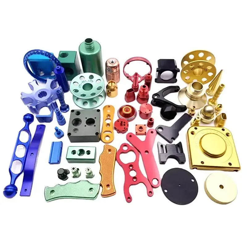
CNC machining prototypes start as a CAD model and end as a solid part cut by rotating cutters and turning tools. Nothing is molded or sintered. Material is removed until the remaining shape matches the file, which is why the process is called subtractive.
That single fact drives most design decisions. Because the part is cut from a block or bar, every internal corner carries the radius of the tool that made it. A square inside corner exists only in CAD. On the machine it becomes a small fillet, usually 0.5 to 3 mm depending on the cutter.
CNC machining prototypes fit cases where the part must behave like a production part. If you need to test thread strength, bearing fit, or drop behavior, a machined prototype gives you real answers. A printed or cast part often gives you an answer about the process, not the design.
The trade-off is cost per unit at high volume. Subtractive cutting wastes stock and machine time. For one part or two hundred, that rarely matters. At ten thousand parts, molding usually wins. The prototype still earns its place because it validates the design before tooling is cut.
Tool Access and Wall Thickness in Your Design
A cutter needs a straight path to the feature it cuts. Deep pockets, undercuts, and cross-drilled holes at shallow angles all shorten the reachable depth. A rule of thumb: pocket depth should stay under four times the cutter diameter, or the tool chatters and the finish degrades.
Undercuts are the classic blocker. If a feature is wider at the bottom than at the opening, no straight end mill reaches it. That leaves three options. Add a side-opening, split the part into two pieces, or move the feature to a 5-axis setup where the table tilts and the tool approaches from a new direction.
Wall thickness matters more than most designers expect. Thin aluminum walls below 0.8 mm deflect under cutting force. Thin plastic walls below 1.5 mm can flex enough to chatter. Both can be machined, but expect slower feeds and a higher risk of scrapping the first part.
Sharp external corners are the opposite problem. They are easy to cut but they chip. A 0.3 to 0.5 mm chamfer or a small radius costs nothing on the machine and removes a common failure point on the finished part.
Material Choice Changes the Tolerances You Can Hold
Not every material holds ±0.005 mm equally well. Aluminum 6061 and 7075 cut clean and stay stable, which is why they are the default for functional CNC machining prototypes. Stainless 304 and 316 work harden, so heavy roughing passes are avoided and tool wear climbs fast.
Titanium TC4 (Ti-6Al-4V) and Inconel sit at the difficult end. They hold tolerance well but cut slowly, generate heat, and need rigid setups. Budget more machine time and expect a narrower choice of cutters. For a fit check, a 17-4PH stainless part is often a cheaper stand-in.
Plastics behave differently again. POM and PEEK machine cleanly and hold tight dimensions. ABS and PP are soft, so they scratch and burr. PMMA is brittle and can craze around a drilled hole. If the prototype needs to look like a production part, the material and the finish have to be chosen together.
Surface finish is part of the same decision. As-machined surfaces land around Ra 1.6–3.2 μm. Bead blasting, tumbling, or polishing push that lower. Anodizing adds a hard layer and a color, but it also adds a few micrometers, which can matter on a press fit.
From CAD File to Machined Prototype in Five Steps
The workflow is short, and each step has a failure mode worth knowing. Most delays trace back to a model that was never checked against the machine before it was released.
First, the CAD file arrives in STEP or IGES form. The engineer reviews it for tool access, thin walls, and features that need a second setup. This DFM pass usually returns within 12 hours and often catches problems that would otherwise surface at the machine.
Second, the CAM programmer builds the toolpaths. Setup count matters here. A part that can be cut in two setups costs less than one needing five, because each setup adds a fixture, an alignment, and a chance for error.
Third, the operator machines the part. Roughing removes most of the stock, then semi-finishing and finishing passes bring the surface to spec. In-process checks catch a drifting dimension before the whole batch is cut.
Fourth, post-processing runs. That covers deburring, bead blasting, anodizing, plating, or laser marking. Laser-marked text needs a minimum character height of 1.5 mm to stay legible.
Fifth, inspection. Every part is checked before shipment, and dimensional reports are available on request. For a prototype, this is where you confirm the design, not just the part.
When CNC Machining Prototypes Are the Wrong Choice
Subtractive machining is not a universal answer. It loses to other processes in three clear situations.
Very complex internal channels are the first. A part with curved cooling passages inside a solid block is difficult to cut and easy to scrap. Additive manufacturing handles that geometry natively, so a printed part is often the better first step.
Large flat panels are the second. Sheet metal fabrication bends and punches those faster and cheaper. Machining a 2 mm thick, 500 mm long bracket from solid stock wastes material for no gain in function.
Very high volumes are the third. Once tooling is justified, die casting or injection molding drives unit cost down far below any cutting process. The machined prototype still has a role, but it becomes a validation step rather than the production method.
There is also a middle ground worth naming. Vacuum casting suits small runs of urethane parts that mimic injection-molded behavior. It pairs well with a machined master pattern.
CNC Machining Prototypes Against Other Prototyping Routes
Pick the route that matches the question you are trying to answer.
| Route | Best for | Typical limit | Watch out for |
|---|---|---|---|
| CNC machining | Functional fit, threads, bearing seats | Deep undercuts need extra setups | Stock waste at high volume |
| 3D printing | Internal channels, lattice, hollow shapes | Weaker layer direction strength | Surface finish needs post-work |
| Sheet metal | Enclosures, brackets, flat panels | Thickness steps and bend radii | Bend relief must be modeled |
| Vacuum casting | Small runs of urethane parts | Mold life is short | Shrinkage changes dimensions |
| Die casting | High volume metal parts | Tooling cost and lead time | Porosity in thick sections |
The Short Version
If the prototype has to prove fit, function, or a threaded joint, cut it from metal. If the geometry is hollow or internal, print it first. The two are not competitors; they answer different questions.
Common Questions
What materials can be used for CNC machining prototypes?
Aluminum grades 6061, 6061-T6, 2024, 5052, 5083, 6063, 6082, 7075, and ADC12 cover most functional prototypes. Stainless 303, 304, 316, 316L, 17-4PH, and 440C handle corrosion and wear requirements.
Steel options include 1018, 1045, 4130, 4140, 4340, and tool steel. Copper and brass grades such as C101, C110, and C36000 work for electrical parts. Titanium TA1, TA2, TC4, Inconel, and magnesium AZ31B or AZ91D are available when weight or temperature demands them.
How long does it take to make a CNC machined prototype?
A quotation and free DFM analysis come back within 12 hours. Production can start within 24 hours of approval, and parts typically ship in 3–5 days.
The main variable is setup count and finishing. A part with five setups and anodizing takes longer than a two-setup part left as machined. Send the drawing early and the schedule is easier to hold.
Can I get just one prototype part?
Yes. There is no minimum order quantity, and the range runs from a single prototype to runs of 10,000 parts or more.
One-off work uses the same machines and inspection as a production run, so the first part tells you what the tenth part will do.
How do I know my design will machine without problems?
Send the STEP or IGES file and we return a DFM review with the quote. It flags thin walls, unreachable features, tight inside corners, and tolerance calls that are tighter than the geometry needs.
Fixing those in CAD costs nothing. Fixing them after the first part is cut costs a setup and a new piece of stock.
Will my design stay confidential?
Uploads are handled as secure and confidential, and a non-disclosure agreement is available on request before files are shared.
If your project needs controlled drawings or restricted distribution, say so in the first message and we set it up before the DFM review starts.
What surface finishes are available on a prototype?
Anodizing comes in clear, color, hardcoat, and conductive types. Plating options include electroless nickel, zinc, silver, and gold. Powder coating and black oxide are also available.
For texture, bead blasting, tumbling, brushing, and polishing all work. Laser marking and engraving handle part numbers and logos, with a minimum character height of 1.5 mm.
Send Your CAD File and Get a DFM Review
Upload a STEP file and we return a quotation with a free DFM analysis within 12 hours, before any metal is cut.
12-hour quote±0.005 mm tolerance100% inspection
More From GreatLight
We publish setup notes, tooling trials and inspection data from the factory floor.











