
PolyJet 3D Printing: How Resin Jetting Actually Works
This guide covers the PolyJet 3D printing process from droplet to cured layer, the material combinations it supports, and the part geometries it cannot hold. It is written for design and manufacturing engineers who need to decide between PolyJet, other additive processes, and CNC machining.
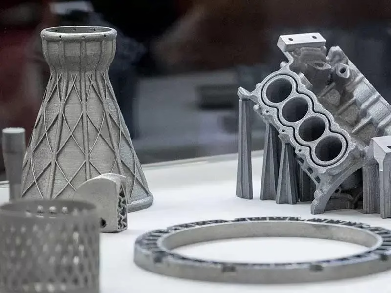
How PolyJet 3D printing builds a part
PolyJet 3D printing is a material jetting process. A print head travels across the build platform and deposits thousands of microscopic droplets of liquid photopolymer, one pass at a time. A UV lamp mounted beside the head cures each pass almost immediately, so the resin goes from liquid to solid in seconds rather than minutes.
The head carries separate nozzle arrays for model material and support material. That split matters. Support is jetted where overhangs, undercuts, and internal channels need it, then removed after the build. Because support is jetted rather than printed as the same plastic, it can be dissolved or blasted away without touching the model surface.
Layer thickness typically runs from 14 µm to 32 µm depending on the machine and the resin. Thinner layers buy you smoother curved surfaces and finer vertical detail, at the cost of build time. A 16 µm layer on a 50 mm tall part takes roughly twice as long as a 32 µm layer on the same geometry.
The build platform indexes down by one layer height after each pass, then the head sweeps again. There is no melting, no powder bed, and no laser. That is why PolyJet parts come out with a smooth as-built surface and why the process tolerates thin walls and small features that powder-based systems struggle to clear.
- 1Droplet sizePicoliter-scale droplets from multiple nozzle arrays
- 2Cure sourceUV lamp trailing the print head, cure within the same pass
- 3SupportJetted separately, removed by water jet or manual tools
- 4Layer range14–32 µm, chosen per job against build time
Multi-material builds and what they are good for
The strongest reason to choose PolyJet 3D printing over other resin processes is material mixing inside one build. A single job can place a rigid opaque shell next to a soft 30 Shore A gasket and a clear window, with the digital model defining where each one lands. No assembly, no adhesive, no secondary bonding step.
Digital materials are the mechanism. The printer blends two base resins at the nozzle level in set ratios to produce intermediate properties. That gives you a continuous range rather than a fixed catalogue. You can dial a durometer between two endpoints, or shift a color, without changing feedstock.
Clear resins are worth calling out. They print transparent and can be polished or dipped to improve clarity, which is useful for light pipes, fluid visualization manifolds, and lens housings in early fit checks. They are not optically clear at the level of a ground glass optic, and they yellow under sustained UV exposure.
Where this helps most: overmold studies, grip and seal prototypes, multi-durometer parts, and any assembly where you want to test the interface between two materials before committing to tooling. Where it does not help: parts that see sustained load, heat above roughly 60–80 °C, or long-term outdoor exposure.
- 1Rigid opaqueSimulates ABS-like housings and brackets
- 2FlexibleElastomer-like resins for seals, grips, and living hinges
- 3TransparentLight pipes and fluid paths; yellows under UV
- 4Digital blendsIntermediate durometer and color, set by the model
Where PolyJet stops being the right answer
PolyJet parts are photopolymers. They are not engineering thermoplastics, and they do not behave like them. Tensile and impact values drop as the resin absorbs moisture and sees UV, and a part left on a windowsill for a year will not measure the same as the day it was built. Treat PolyJet output as a dimensional and ergonomic model, not a service part.
Heat is the other hard limit. Most PolyJet resins soften well below the range where a machined aluminum or PEEK part keeps working. If your prototype sits near a motor, an exhaust path, or a soldering operation, the resin will creep or sag. That is a material property, not a print setting you can tune out.
Threads and press fits are a common trap. Printed threads under M6 are fragile and strip easily. Better to print a pilot hole and cut the thread with a tap, or design in a heat-set insert boss with enough wall thickness. Press fits need a printed slip allowance and a real pin, not a printed pin.
When the part has to carry load, seal against pressure, or hold ±0.005 mm across a mating face, the answer is usually machining. We run 127 high-precision CNC machines across 3 wholly-owned plants, including 16 simultaneous 5-axis centers, and the tolerance we hold is ±0.005 mm (±0.0002 in) with finishes down to Ra 0.2–0.8 μm. That is a different class of part from a jetted resin model.
- 1HeatResins soften far below metal or PEEK service temperatures
- 2UV and moistureProperties drift over months, not years
- 3Printed threadsFragile under M6; tap or use heat-set inserts
- 4Load pathsMove to machined metal when the part carries real stress
Design rules that keep PolyJet parts usable
Design for support removal from the start. Any internal channel needs a path for the support to exit, either through an open end or a drain hole. A closed cavity traps support and you will not get it out without cutting the part. Aim for a minimum channel of about 1 mm and give it two openings where geometry allows.
Wall thickness below roughly 0.5 mm gets unpredictable. Thin walls print, but they curl and they are hard to measure. If a wall is structural in your design intent, keep it at 1 mm or above. If it is a membrane or a living hinge, print a test strip first and flex it before you commit the whole geometry.
Orientation drives both surface finish and build time. The top face of a build is the smoothest because it is the last layer. Vertical faces carry the layer stair-step. If one face has to look good, rotate the model so that face points up, then accept the finish elsewhere.
Shrinkage is small but real, and it varies by resin and geometry. For parts that must mate with a machined counterpart, print a test coupon with the same wall section and measure it before you release the full model. A 0.1 mm error on a printed boss is normal. The same error on a machined bore is not.
- 1Support escapeGive every internal channel a drain path
- 2Minimum wall0.5 mm floor, 1 mm for anything structural
- 3OrientationPoint the critical cosmetic face upward
- 4ShrinkagePrint a coupon before releasing mating geometry
From CAD file to finished PolyJet part
- 11. Check the meshExport STL or 3MF and repair non-manifold edges. Slicers reject open shells and will not let you place support correctly.
- 22. Assign materials per bodySplit the model into separate bodies for each durometer, color, or clarity. The slicer maps one material to one body.
- 33. Choose layer heightUse 14–16 µm for fine features and smooth curves, 28–32 µm for large form checks where build time matters more.
- 44. Place supportLet the slicer generate it, then review undercuts and internal channels. Add drain paths if support has nowhere to go.
- 55. Orient for finishRotate the build so the critical face points up. Confirm the part fits the build envelope before slicing.
- 66. Print and cureRun the build, then remove support with a water jet or hand tools. Do not soak clear parts longer than needed.
- 77. Measure and finishCheck critical dimensions, then sand or polish if clarity or surface feel matters. Log the as-built numbers.
PolyJet compared with other routes
Pick by the property your part actually has to hold, not by the process name.
| Route | Best for | Watch out for |
|---|---|---|
| PolyJet | Fine detail, multi-material, smooth as-built | Low heat resistance, resin ages under UV |
| SLA / DLP | Single-material fine detail and smooth finish | One material per build, limited color |
| SLS / MJF | Functional nylon parts, snap fits, small batches | Grainy surface, no clear or soft options |
| FDM | Large cheap form checks and jigs | Visible layer lines, weak in Z direction |
| CNC machining | Tight tolerance, real metal, load-bearing parts | Higher unit cost at very low volume |
The short verdict
If the part is a fine-detail, multi-material form and fit model, PolyJet 3D printing is the fastest route. If it carries load, seals, or holds a tight tolerance, machine it instead — our quote and free DFM analysis come back within 12 hours.
PolyJet questions engineers actually ask
How tight a tolerance can PolyJet hold?
Expect roughly ±0.1 mm on a well-oriented part, and treat that as a guide rather than a guarantee. Shrinkage varies by resin, wall section, and geometry, so the number moves.
For mating features, print a coupon with the same section and measure it. If the interface needs ±0.005 mm, that is a machining job, not a jetting job.
Can PolyJet parts be used as functional end-use parts?
Usually no. The resins are photopolymers, and their mechanical properties drift with UV and moisture exposure. They creep under sustained load and soften well below the temperatures a metal or PEEK part handles.
Use them for form, fit, ergonomics, and assembly checks. For anything that carries load or sees heat, move to machining.
How do you remove support material without damaging the part?
Support comes off with a water jet at controlled pressure, plus hand tools for tight corners. The key is design: give internal channels a drain path so support has somewhere to exit.
Do not soak transparent parts longer than needed. Prolonged soaking clouds the surface and you lose the clarity you printed for.
What is the largest part PolyJet can produce?
Build envelopes vary by machine and are much smaller than our CNC capacity, where we machine parts up to 4,000 mm. PolyJet is a small-to-medium part process.
If your geometry exceeds the envelope, the usual fix is to split the model into sections and bond them. That adds a joint, so plan the split line where it will not sit on a critical face.
Is PolyJet more expensive than SLA or SLS?
Per part, usually yes. The multi-material capability and the fine layer heights cost more to run than a single-material resin or powder process.
The trade is design freedom. If one build replaces three separate prints and an assembly step, the total cost often lands lower. Compare the whole path, not the per-part rate.
Can you combine PolyJet prototypes with machined metal parts?
Yes, and it is a common approach. Print the housing or cover in resin, machine the load-bearing bracket or heat path in aluminum or stainless, then assemble and test.
We machine aluminum, stainless, steel, copper, brass, titanium, and engineering plastics, and we offer anodizing, plating, powder coating, and bead blasting to match the prototype to production appearance.
Send the model, get a real answer
Upload your CAD file and we will tell you whether PolyJet, machining, or a mix of both fits the part. Quotation and free DFM analysis within 12 hours.
12-hour quote100% inspectionNo minimum order quantity
More from the shop floor
We publish setup notes, tooling trials and inspection data from the factory floor.











