
3D Nylon Printing: A Practical Guide for Engineers
This guide covers how nylon behaves in 3D nylon printing, which of the three common processes fits a given part, and where the material stops making sense. It is written for design and manufacturing engineers who need to pick a route before cutting a purchase order. By the end you should be able to read a drawing, name the nylon grade and process, and know whether to print or machine it.
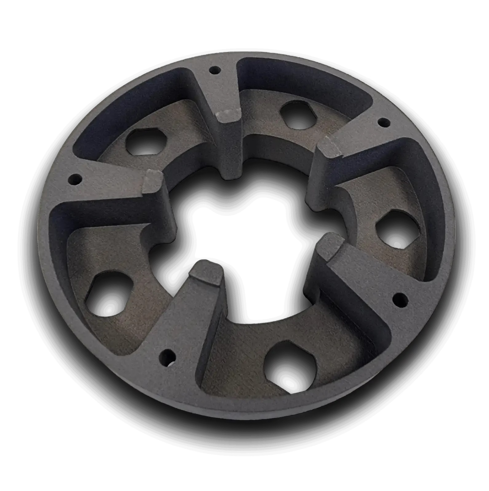
What this guide covers
Nylon is one of the few polymers that survives real load, repeated impact and sliding contact. It is also one of the hardest to print well.
What nylon actually is, and why it prints differently
Nylon is a polyamide, a semi-crystalline polymer held together by hydrogen bonds between amide groups along the chain. Those bonds give it toughness, abrasion resistance and a low friction coefficient, which is why it shows up in gears, bushings, hinges and living hinges. The same crystallinity makes the melt behave badly. Nylon has a sharp melting point and a narrow processing window.
Moisture is the other problem. Dry PA 12 pellets absorb around 0.5 percent water in open air, and PA 6 can take up 2 to 3 percent. Wet powder or filament produces voids, poor layer bonding and weak parts. Every serious shop dries powder and filament before a build, then keeps it in a dry box between jobs.
Printed nylon is not the same as molded or machined nylon. Layer-by-layer deposition and laser fusion both leave porosity, so a printed part absorbs more water and loses strength faster in a humid environment. That gap matters if the part sees continuous load or tight tolerances.
SLS, MJF and FDM: how to choose
SLS, or selective laser sintering, spreads a thin layer of nylon powder and fuses it with a laser. Unfused powder supports the part, so you can build interlocking geometry, nested assemblies and internal channels with no support removal. The surface comes out matte and slightly grainy, roughly Ra 10 to 15 μm, and the part is isotropic in the XY plane but weaker across the Z axis.
MJF, or multi jet fusion, works on the same powder bed principle with a different energy source. A fusing agent is jetted onto the powder and infrared lamps cure the layer. MJF runs faster than SLS and produces a slightly better surface, but the agent chemistry limits the available grades. PA 12 and PA 11 are the standard options. Both powders can be blended with glass beads or aluminum flakes for stiffness.
FDM, or fused deposition modeling, pushes nylon filament through a heated nozzle. It is the cheapest entry point and the only one that handles PA 6 and PA 66 well, but it needs a heated chamber and a hardened nozzle. Layer adhesion is the weak point. FDM nylon parts split along layer lines under peel or impact load, so keep the load path in-plane.
- 1Pick SLScomplex geometry, small batches, no supports, good all-round mechanicals
- 2Pick MJFlarger runs, faster turnaround, tighter surface, PA 12 or PA 11 only
- 3Pick FDMPA 6 or PA 66, simple shapes, lowest tooling cost, in-plane loads
Nylon grades and where each one fits
Typical values for printed parts. Actual numbers depend on build orientation, powder blend and conditioning.
| Grade | Best process | Notable property | Watch out for |
|---|---|---|---|
| PA 12 | SLS, MJF | Low moisture uptake, good chemical resistance | Lower impact strength than PA 11 |
| PA 11 | SLS, MJF | High elongation, UV and impact resistance | Higher cost per kilogram |
| PA 6 | FDM | High strength and wear resistance | Absorbs moisture fast, needs drying |
| PA 66 | FDM | Higher melting point, stiffer | Harder to print, warps without a heated chamber |
| PA 12 + glass bead | SLS, MJF | Higher stiffness, better dimensional stability | Lower elongation, more abrasive |
| PA 12 + aluminum | SLS, MJF | Metal-like stiffness and thermal conductivity | Heavier, limited color options |
Design rules that keep printed nylon parts usable
Minimum wall thickness depends on the process. SLS and MJF hold 0.8 mm walls, but 1.2 to 1.5 mm is a safer floor if the wall carries load or gets handled. FDM needs 1.2 mm or more because each extrusion bead is 0.4 to 0.6 mm wide and thin walls print as a single sparse line. Stay under 6 mm on solid sections or the part becomes a heat sink and cools unevenly.
Holes and bosses behave differently from machined parts. Printed holes come out undersized, typically 0.1 to 0.3 mm smaller than the model, because the fusion zone pulls inward. Design the hole at nominal plus 0.2 mm if it is a clearance hole. For a press fit, print undersized and ream to size. Threaded bosses work better with a heat-set insert than with printed threads.
Tolerances are the real limit. SLS and MJF hold around ±0.3 mm on small parts and ±0.5 mm on long dimensions, plus a percentage of the overall size. That is not interchangeable with CNC work. If a bearing bore, a sealing face or a shaft fit matters, plan a machining operation after printing, or machine the part from PA stock instead.
- 1Clearancesleave 0.3 mm for moving fits, 0.15 mm for a light press
- 2Draftnot needed for powder bed processes, useful for FDM release
- 3Orientationkeep tensile load out of the Z axis on SLS and MJF
- 4AnisotropyFDM parts can lose 40 percent strength across layers
Dyeing, sealing and surface finishing
Raw SLS and MJF parts come out gray and slightly porous. Dyeing in a heated water bath gives an even color but only penetrates a fraction of a millimeter, so wear and scratches expose the gray base. Vapor smoothing with solvent closes the surface and raises gloss, though it softens edges and needs tight process control. Neither treatment makes the part watertight under pressure.
If the part needs a sealed, smooth or dimensionally critical surface, machining is the reliable answer. We cut PA and other engineering plastics on the same CNC floor as aluminum and stainless, holding ±0.005 mm and finishes down to Ra 0.2–0.8 μm. That covers sealing faces, bearing bores and mating surfaces that a printer cannot hold.
A common route is a hybrid: print the complex body, then machine the critical features. This keeps printing cost low where geometry is complicated and puts tolerance where it matters. Send us the drawing and we will mark which faces need machining and which can stay as-printed.
When 3D nylon printing is the wrong choice
Skip printing when the part sees continuous high load, high temperature or tight tolerances. Printed nylon creeps under sustained stress, especially above 60 °C, and it loses stiffness in boiling water or steam. Autoclave cycles and engine-bay heat will deform it.
Skip printing when you need 10,000 identical parts with a fixed dimension. At that volume, injection molding or CNC machining wins on unit cost and repeatability. Printing stays competitive for one-off fixtures, low-volume runs, spare parts and geometry that would be impossible to machine.
Skip printing when the surface finish is a functional requirement. A printed surface cannot seal against an O-ring or slide against a shaft without post-machining. For those features, plan the secondary operation from the start.
Common questions about 3D nylon printing
How strong is a printed nylon part compared with a machined one?
Printed nylon is weaker across layers and slightly porous, so it absorbs water and creeps faster under load. In-plane strength on SLS and MJF is close to molded nylon, but the Z direction can be 30 to 50 percent lower.
For a load-bearing bracket or a press-fit bore, machined PA stock is the safer choice. We hold ±0.005 mm and Ra 0.8–1.6 μm on plastics, which a printer cannot match.
Which nylon grade should I specify?
PA 12 is the default for most functional parts: low moisture uptake, good chemical resistance and stable dimensions. PA 11 gives higher elongation and better impact and UV performance, at a higher price.
Use PA 6 or PA 66 only on FDM, and only if you need higher strength and wear resistance. Both absorb moisture quickly and need drying before and between builds.
Can printed nylon parts be dyed or painted?
Dyeing works well on SLS and MJF parts. The dye penetrates a shallow layer, so color fades where the surface wears. Painting needs a primer because nylon has low surface energy and most paints bead up.
For a durable finish, plan a machined surface and then anodize or coat a metal part instead. That route is common when color and wear resistance both matter.
What wall thickness and hole size should I design for?
Keep walls at 1.2 to 1.5 mm or thicker for SLS and MJF, and 1.2 mm minimum for FDM. Holes print undersized by roughly 0.2 mm, so add that to clearance holes and ream press fits to size.
Threaded features hold up better with a heat-set insert than with printed threads. Leave a boss diameter of at least twice the insert diameter.
Do you offer 3D printing alongside CNC machining?
Yes. We run custom 3D printing for prototypes and low-volume parts, and 127 high-precision CNC machines for the features that need tolerance. One shop handles both, so you do not manage two suppliers.
We can also start from a printed prototype and move to machined or molded production as volume grows. No minimum order quantity, from one part to 10,000+.
How do I get a quote and how fast?
Upload your model and drawing through the quote page. We return a quotation and a free DFM analysis within 12 hours, and production can start within 24 hours after approval.
Parts ship in 3–5 days for standard work. Uploads are kept secure and confidential, and we sign an NDA on request.
Print it, machine it, or both
Send your model and drawing. We will tell you which process fits the part and quote both routes.
12-hour quoteFree DFM analysisNo minimum order









