
PEEK in 3D Printing: A Durable and Demanding Material
PEEK is one of the few thermoplastics that can replace metal in a hot, chemically aggressive part. It is also one of the hardest polymers to print. This page explains what happens inside the nozzle and the chamber, where printed PEEK holds up, and where it does not.
In this article
- 1
- 2
- 3
- 4
- 5
- 6
- 7
- 8
Key takeaways
What PEEK actually is, in numbers
Polyetheretherketone is a semi-crystalline thermoplastic built from aromatic rings linked by ether and ketone groups. That backbone is stiff and thermally stable, which is why the numbers look unusual for a plastic. Glass transition sits at 143 °C and the crystalline melting point at 343 °C. A part can run continuously near 250 °C and still hold most of its room-temperature stiffness.
The aromatic rings also resist attack. PEEK shrugs off most fuels, hydraulic fluids, weak acids and steam, which is why it shows up in pump internals, valve seats and aircraft brackets. Unfilled PEEK has a tensile strength around 90–100 MPa and a modulus near 3.6 GPa. Add 30% carbon fiber and the modulus roughly triples while wear resistance improves.
For an engineer, the useful way to think about PEEK is as a metal substitute that is 4–5 times lighter than steel. It does not conduct heat or current. It does not gall. Those three properties, not raw strength, are usually what drives the material choice.
The catch is that all of these properties assume a fully dense, fully crystallized part. FDM printing gives you neither by default. It gives you a stack of bonded beads with whatever crystallinity the cooling history allowed.
Why PEEK in 3D printing is hard: melt, flow, then freeze
PEEK is printed almost exclusively by fused deposition modeling. The filament is pushed through a nozzle held between 380 °C and 430 °C. At that temperature the melt viscosity is still high, roughly an order of magnitude above PLA or ABS at their own print temperatures. High viscosity means the polymer does not flow into corners the way a low-viscosity melt does, so toolpaths need wider extrusion widths and slower speeds.
The second requirement is chamber temperature. If the deposited bead cools below 143 °C before the next layer lands, it cannot co-crystallize with the layer above. The result is a weak, glossy interface that splits under load. High-temperature printers therefore hold the build chamber at 200 °C or higher, often with a heated bed above 120 °C. That is the single feature that separates a PEEK-capable machine from a general-purpose one.
The third factor is shrinkage during crystallization. Semi-crystalline polymers contract measurably as the disordered melt orders into crystals. PEEK does this over a temperature range that overlaps with the printing window. Large flat parts and thick sections therefore curl and delaminate unless the chamber is uniform and the geometry is managed.
None of this is a defect in the material. It is simply the price of a polymer that stays useful at 250 °C.
- 1Nozzle380–430 °C, hardened or high-temp hotend, 0.4–0.6 mm typical
- 2Chamber200 °C or above for layer bonding and crystallinity
- 3Bed120–160 °C, often on a PEI or PEEK build plate
- 4Post-processControlled anneal, then slow cool to avoid stress cracking
Direction matters more than the datasheet
A printed PEEK part is not isotropic. In the XY plane, where the extruded bead runs continuously, tensile strength can reach 80–90% of the injection-molded value. Across the layers, in Z, it often falls to 40–60%. The gap widens if the chamber ran cool or the layer time was too long.
That ratio drives design decisions more than any single material number. A bracket loaded in shear across its layers will delaminate long before the same bracket loaded in-plane. If the load path must cross layers, thicken the section, raise the extrusion temperature slightly, and keep the layer time short so each bead lands on a still-warm surface.
Porosity is the second hidden variable. PEEK outgasses and picks up moisture, and any water in the filament flashes to steam in the nozzle. The result is microvoids along the bead, which act as crack starters in fatigue. Drying the filament before a run is not optional. Most PEEK grades should sit in a 120–150 °C oven for several hours before printing.
A printed part can be strong. It is rarely strong in every direction.
Where printed PEEK pays off, and where it does not
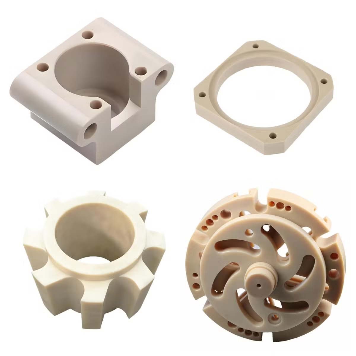
Printed PEEK earns its cost in low-volume, high-value parts where the geometry is complex and the environment is hostile. A ducting elbow with internal channels, a custom impeller, a surgical guide, a test fixture that runs inside an autoclave. These are parts where machining would need many setups or would not reach the internal features at all.
It also wins during development. A printed PEEK manifold can be on a test rig within days, letting a team validate flow and fit before committing to tooling. The printed part may not be the production part, but it answers the same engineering questions.
Printed PEEK does not win on tight tolerances. FDM holds roughly ±0.2 mm on a good day, and warping pushes that wider on tall or flat geometry. It does not win on void-free walls either, and it does not win when the part sees cyclic load across layers.
In those cases the answer is usually machined PEEK stock. Compression-molded or extruded rod and plate are fully dense and fully crystallized. Milling or turning that stock holds ±0.005 mm, produces no layer interface, and can be inspected like any metal part.
How to choose between printing and machining PEEK
Start with the load direction. If the highest stress crosses layer planes, machining is the safer default. If the load stays in the plane of the beads, printing stays in play.
Then check the tolerance callouts. Anything tighter than ±0.1 mm on a mating feature points to machining, because printed PEEK will need post-machining anyway and that defeats the purpose of printing it.
Then look at the internal geometry. Printing is the only practical route when a part needs a curved internal passage, a lattice, or a cavity a cutter cannot reach. Machining wins when the part is a turned bushing, a flat seal face, or a manifold that can be drilled from three sides.
Finally, count the parts. Printing makes sense for a handful of units or a design that is still moving. Above a few hundred identical pieces, the setup cost of machining spreads out and the per-part economics flip.
Running PEEK on a high-temperature printer
Sequence matters as much as the setpoints.
- 1Dry the filamentHold PEEK at 120–150 °C for 4–6 hours. Print from a heated dry box if the run is long.
- 2Soak the chamberBring chamber to 200 °C or above and bed to 120–160 °C before the first layer. Let it stabilize.
- 3Set the meltNozzle 380–430 °C depending on grade. Unfilled PEEK sits near the low end, CF grades near the top.
- 4Slow the depositionKeep layer times short so each bead lands on a warm surface. Reduce speed rather than raising temperature.
- 5Manage the first layerSlight over-extrusion on layer one. A wide brim helps on flat parts that want to curl.
- 6Anneal in placeCool from chamber temperature slowly, in steps. Fast cooling locks in stress and lowers crystallinity.
- 7Inspect and finishCheck for delamination and voids. Machine critical faces afterward if the drawing demands it.
Printed PEEK vs machined PEEK: pick by requirement
Use this when the drawing is fixed but the process is still open.
| Requirement | Printed PEEK | Machined PEEK stock |
|---|---|---|
| Internal channels | Complex paths, one build | Limited by tool reach |
| Tolerance | About ±0.2 mm | ±0.005 mm |
| Layer interface | Present, weak in Z | None, isotropic |
| Porosity | Microvoids possible | Fully dense |
| Lead time | Days for a small batch | 3–5 days after DFM |
| Surface finish | Ra 8–15 μm as printed | Ra 0.8–1.6 μm typical |
| Best volume | One to a few hundred | One to 10,000+ parts |
| Wall thickness | Needs 1.5 mm or more | 0.5 mm feasible |
The verdict
If the part has internal channels or is still changing, print it in PEEK. If it needs ±0.005 mm, a void-free wall, or load across layers, machine it from PEEK stock instead.
PEEK in 3D printing: common questions
Can a normal FDM printer run PEEK?
No. A standard printer tops out around 300 °C at the nozzle and has no heated chamber, so the melt never reaches the 380–430 °C window and layers bond poorly.
PEEK needs a machine rated for 400 °C or higher plus a chamber held above 200 °C. That combination is what makes the material printable at all.
Does printed PEEK need annealing?
Usually yes. As-printed PEEK can be partly amorphous if it cooled quickly, which leaves it softer and less chemically resistant than the datasheet values.
A controlled anneal above the glass transition temperature lets the crystals form, then a slow cool relieves the stress that built up during the build.
How strong is printed PEEK compared with machined PEEK?
In the plane of the layers, printed PEEK reaches roughly 80–90% of molded strength. Across the layers it drops to about 40–60%.
Machined PEEK from compression-molded stock is fully dense and isotropic, so it has no weak axis and no layer interface.
Is PEEK the same as PEKK for printing?
They are close relatives, not the same polymer. PEKK melts lower and crystallizes more slowly, which gives a wider process window and less warping.
PEEK holds a slightly higher continuous service temperature. The choice usually comes down to which printer you have and how much warping you can tolerate.
What is the minimum wall thickness for printed PEEK?
Plan on 1.5 mm or more for a wall that carries load. Thinner walls print, but the bead count drops to two or three and the part becomes sensitive to voids and warp.
If the design needs a 0.5 mm wall, that is a machined PEEK part, not a printed one.
Can printed PEEK parts be machined afterward?
Yes, and it is common. Printing gets the near-net shape with internal features, then milling or turning brings the critical faces into tolerance.
Do the machining after annealing, not before. Stress relief moves the part, and you do not want that movement to happen after the final cut.
Send us the PEEK part and the drawing
We review the geometry, tell you whether printing or machining is the better route, and quote it. DFM feedback within 12 hours.
12-hour quoteFree DFM analysisNDA on requestNo minimum order quantity
More from the shop floor
We publish setup notes, tooling trials and inspection data from the factory floor.











