
Optimization and improvement of the CNC lathe farm robot
A gantry loader feeding a row of lathes is one of the most predictable automation cells you can build, and one of the easiest to get wrong. This page explains how a CNC lathe farm robot actually moves a part through the cycle, where the time goes, and which changes are worth making. Written for process engineers and maintenance leads who already have a cell running or are quoting one.
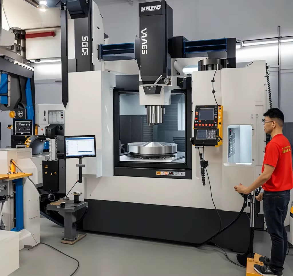
What a lathe farm robot actually does
A lathe farm is a row of turning centers served by one handling system, usually a gantry or truss frame mounted above the machines. The robot does not cut metal. It picks a blank from a tray or conveyor, carries it along a linear axis, drops it into the chuck, waits for the cut, then removes the finished part and places it on an outfeed station. Everything else in the cell supports those four moves.
That narrow job description is why optimization is tractable. You are not tuning a general-purpose arm with six joints and a vision system. You are tuning a single-axis or three-axis Cartesian motion, a gripper, and a handshake with the machine tool. Most of the lost time and most of the scrap sit in those three places, not in the robot frame itself.
The truss design matters for a practical reason. A stiff frame lets the Z axis travel fast without ringing. On a 1,200 mm horizontal stroke, a gantry that flexes will show up as part seating errors at the chuck and as position drift after a few hundred thousand cycles. Stiffness is not a comfort feature. It is what keeps the repeatability you paid for.
One more boundary. A farm robot suits parts that are light enough to handle, round or near-round, and produced in volumes that justify the tray logistics. If a part weighs 30 kg or changes shape every week, the same frame becomes a liability and a robot arm with a tool changer usually wins.
Where the cycle time goes
Split the cell cycle into machine time and handling time. Machine time is the cut, and the robot cannot do much about it except keep the chuck fed. Handling time is everything else: travel to the tray, grip, lift, travel to the chuck, orient, insert, release, retract. On a typical turning job with a 40 second cut, handling is often 8 to 14 seconds of the total. That is the budget you are optimizing.
Travel is the first target. Acceleration and deceleration dominate short moves. If the gantry reaches 60 m/min on a 300 mm stroke, it spends most of the move ramping. Raising top speed does nothing. Reducing moving mass or softening the acceleration profile with an S-curve usually buys more than a bigger servo.
The second target is the wait. Many cells idle the robot during the cut, then rush the swap. Better sequencing overlaps the outfeed of part N with the infeed of part N+1, so the chuck is never empty longer than the swap itself. On a two-spindle or twin-turret lathe, this overlap can recover several seconds per part without touching the robot hardware at all.
The third target is the handshake. Door open, chuck unclamp, chuck clamp, door close, cycle start. Each signal has a delay and a confirmation. Audit the PLC ladder for dwell timers left at commissioning defaults. Removing a 0.3 second dwell on four signals returns 1.2 seconds per part, which is real money across a year.
Gripper design decisions that decide part quality
The gripper is the only part of the cell that touches the workpiece, so it sets the ceiling on surface quality. For a turned part with a finished OD, hard steel jaws will leave witness marks no matter how careful the motion is. Soft jaws machined to the part diameter, or urethane pads, spread the load and leave the finish intact.
Grip force is a trade, not a maximum. Too little force and the part slips during a fast traverse. Too much and a thin-wall part deforms before it ever reaches the chuck, so the lathe cuts an oval that measures fine on the robot and fails on the CMM. For thin-wall aluminium, regulated air at 0.2 to 0.3 MPa is often enough on a light part.
For parts that are not round, add a mechanical orientation feature rather than relying on servo positioning. A keyed jaw or a spring-loaded pin costs little and removes an entire class of misloads. It also makes the cell tolerant of a slightly bent blank, which matters when the upstream process is a saw.
Dual grippers are worth the extra mass on most farms. One jaw holds the raw blank, the other holds the finished part. The swap becomes a single motion at the chuck instead of a round trip to the tray, and the machine spindle is open for a shorter window.
When gantry automation stops paying off
Automation has a floor and a ceiling. Below roughly a few thousand parts per year per machine, the tray handling and changeover effort eat the savings. Above a certain part size, the gantry and gripper mass needed to move the workpiece makes the frame uneconomical compared with a floor-mounted robot.
Part variety is the other boundary. A farm robot is happiest with a family of parts that share a blank diameter and a grip feature. When every job needs a new gripper, a new tray nest, and a new program, the setup time per job climbs and the cell spends more hours being retooled than running.
Chip control matters more than most teams expect. A gantry that reaches into the work zone will drag stringy chips back to the tray if the turning insert is not breaking them. That is a cutting-tool problem showing up as a robot problem. Fix the chipbreaker and the gripper stops jamming.
Finally, think about what happens when the cell stops. A single gantry over six lathes means one fault idles six spindles. Duplex the critical sensors, keep a spare gripper assembly on the shelf, and write the recovery procedure so an operator can clear a misload without calling an integrator.
The machined parts inside the cell
Gantry frames, robot arm joints, gripper bodies, tray nests, and end-effector brackets are all machined parts, and they are the parts that set the cell's accuracy. A joint housing with a loose bore tolerance will not hold position, no matter how good the servo tuning is.
We machine these components from 6061-T6 and 7075 aluminium when weight matters, and from 4140 or 17-4PH stainless when the bracket sees repeated impact. Tolerances down to ±0.005 mm and finishes of Ra 0.8–1.6 μm are standard for bearing bores and mating faces. For a gripper jaw that touches a finished surface, we usually go finer, to Ra 0.2–0.8 μm.
Because the farm robot runs unattended, the parts inside it need to survive millions of cycles. That means hard anodizing or electroless nickel on wear surfaces, and it means thinking about how a bracket is fastened, not just how it is cut. A joint that loosens after 200,000 cycles is a design fault, not a maintenance problem.
If you are building or rebuilding a cell, send us the joint housings, brackets, and gripper bodies as a set. Machining them together keeps the datums consistent, which is cheaper than fixing alignment at assembly.
Where time is lost and what fixes it
Handling time only; machine time is set by the cutting parameters.
| Symptom | Likely cause | Fix |
|---|---|---|
| Long swap, short cut | Robot idles during cut | Overlap infeed and outfeed |
| Ringing at full speed | Frame or arm too compliant | Add mass damping, soften accel |
| Part not seated in chuck | Insertion force too high | Reduce push force, add seat sensor |
| Gripper marks on finish | Hard jaws, wrong grip force | Soft jaws, regulated air pressure |
| Random cycle stops | Handshake dwell, sensor chatter | Audit PLC timers, debounce inputs |
| Drift after 6 months | Wear on linear guides | Re-lube schedule, check preload |
The verdict
If your part family is stable and volumes are high, optimize the existing gantry: overlap the swap, cut PLC dwells, and fix the gripper. If part variety is growing, stop tuning the robot and move to a flexible arm cell instead.
Questions engineers ask next
How long should a chuck swap take on a gantry loader?
On a part under 2 kg, a well-tuned swap runs 3 to 5 seconds from door open to cycle start. If you are above 7 seconds, look at the PLC handshake before you look at the servo.
The swap time is dominated by confirmation signals, not by the robot's top speed.
Can a lathe farm robot handle a part with an interrupted cut?
Yes, but the gripper has to hold it through the impact. Interrupted cuts push the part back into the jaws on every revolution. Use a positive stop shoulder in the jaw rather than friction alone.
If the part walks in the chuck, the finished length will drift even though the robot positions correctly every cycle.
What repeatability should we expect from a truss gantry?
A stiff truss frame with ground linear guides typically holds ±0.02 mm at the gripper over a 1,000 mm stroke when the frame is anchored properly. The robot itself is rarely the limit.
Most seating errors come from gripper compliance or from a chuck that is not clean, not from the gantry axis.
Do we need a force sensor on the insertion axis?
Not on every cell, but it helps on parts with a tight bore or a chamfer that can catch. A simple current-monitoring check on the Z servo detects a missed seat without extra hardware.
A dedicated load cell gives a clearer signal and lets you log insertion force over time, which is useful for predictive maintenance.
How do we keep chips out of the gripper?
Start with the turning insert. If the chipbreaker is producing long strings, no amount of air blast will keep the gripper clean.
Add a short air blast at the chuck and a chip deflector on the gantry path. Inspect the jaw serrations monthly for packed chips.
What spare parts should be on the shelf?
One complete gripper assembly, a set of soft jaws, the Z-axis belt or coupling, and the door interlock sensors. Those four cover most unplanned stops.
Keeping a spare gripper means a misload costs minutes instead of a shift.
Send us the parts that make the cell accurate
Upload your joint housings, gripper bodies, and brackets. We return a quotation and a free DFM analysis within 12 hours, with production able to start in 24 hours.
12-hour quote±0.005 mmNo minimum order quantityNDA on request
More from GreatLight
We publish setup notes, tooling trials and inspection data from the factory floor.











